Modification of tag fields in Ethernet data packets

Inactive Publication Date: 2005-12-13
3COM TECH +1
View PDF30 Cites 60 Cited by
  • Summary
  • Abstract
  • Description
  • Claims
  • Application Information

AI Technical Summary

Benefits of technology

[0007]The present invention avoids the difficulties of techni...

Problems solved by technology

If the devices are represented by different chips in a multi...

Method used


Image

  • Modification of tag fields in Ethernet data packets
  • Modification of tag fields in Ethernet data packets
  • Modification of tag fields in Ethernet data packets

Examples


Embodiment Construction

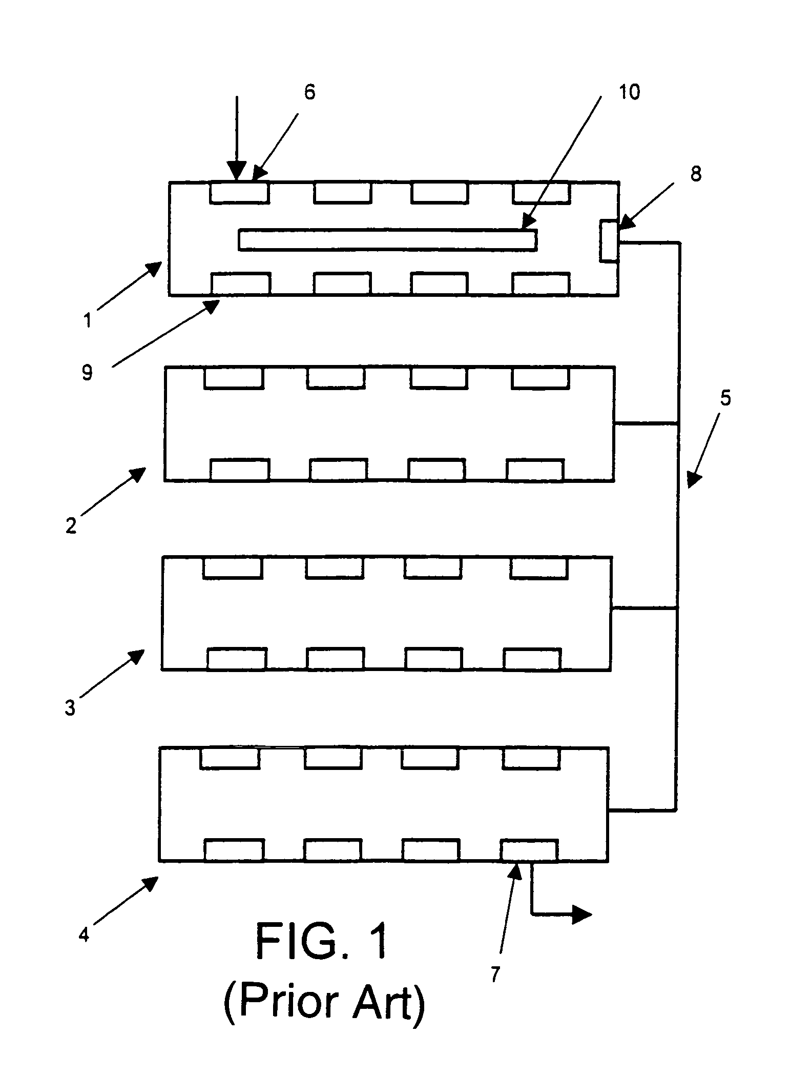
[0015]FIG. 1 of the drawings illustrates schematically only a typical context where the present invention may be employed. The context is a ‘stack’ of similar network devices 1, 2, 3 and 4 which are connected, preferably by means of a cascade connection 5, to form in essence a single logical unit. One description of a cascade connection between network units is described in U.S. patent Ser. No. 09 / 207,655 filed 9 Dec. 1998 (and now U.S. Pat. No. 6,330,245) and incorporated herein by reference. In the example given, devices 1 to 4 may be multi-port devices each having a multiplicity of ports at which data packets may be received and from which data packets may be forwarded. A single device in isolation would, if performing a switching function, typically perform in processing means 10 some examination of address data in the header portion of a receive packet and by means of a forwarding database determine the port from which the packet should be dispatched. The cascade connection 5 e...


PUM


Abstract

An Ethernet data packet including a VLAN tag header and a VLAN identification field is modified. The modification is accomplished by inserting in place of the VLAN tag header a field of the same size including selected information. The VLAN identification may be retained. The inserted field may include a first field indicating the presence of the VLAN identification field and a second field of selected information, the second field being longer than the first field.

Description

BACKGROUND TO THE INVENTION[0001]The present invention relates to packet-switched data communication systems, and particularly to such systems operating according to the IEEE 802.1 transmission standard.[0002]Data communication systems of this general character provide for communication between various parts of a network by means of physical devices that in general comprise a multiplicity of ports and direct received packets from one or more to one or more ports either indiscriminately, in the case of a hub, or selectively, in the case of a switch. The term “switch” is used herein to embrace more specifically named devices, such as bridges, routers or devices that combine both bridging and routing functions.[0003]In a variety of circumstances it is desirable to be able to couple a plurality of devices, such as a multiplicity of hubs or switches, together so that from the point of view of the external network, the plurality of coupled or “stacked” devices acts as a single logical ent...

Claims


Application Information

Patent Timeline
IPC IPC(8): H04L12/46H04L29/06
CPCH04L12/4666H04L29/06H04L69/22H04L9/40
Inventor PARRY, ROBINDRUMMOND-MURRAY, JUSTIN ALAW, DAVID JO'KEEFFE, DANIEL M
Owner 3COM TECH
Why Eureka
Try Eureka