
Active control system and method for reducing disk fluttering induced track misregistrations

a technology of active control system and disk fluttering, applied in the direction of magnetic recording, information storage, maintaining head carrier alignment, etc., can solve the problems of narrow bandwidth mechanical disturbance, so as to facilitate incorporation and not affect the stability of the system

Inactive Publication Date: 2005-05-03
AGENCY FOR SCI TECH & RES
View PDF28 Cites 52 Cited by
  • Summary
  • Abstract
  • Description
  • Claims
  • Application Information

AI Technical Summary

Benefits of technology

[0019]By monitoring movement of the actuator in an axial direction relative to the disk, that is, perpendicular to the disk surface, the present invention provides a manner in which disk flutter may be monitored. As disk flutter causes the read / write head to move, via the air bearing surface (ABS), axial movement of the read / write head and thus the actuator is representative of disk flutter, typically being approximately proportional to disk flutter. Hence, measurement of movement of the actuator in an axial direction relative to the disk enables compensatory control signals to be generated from the output signal of the means for detecting, in order to counteract the effects of disk flutter, and in particular, to counteract disk-utter induced off-track deviation of a read / write head supported by the actuator. For instance, the control signals may have an amplitude which is proportional to an amplitude of the output signal of the means for detecting, and may have a corrected phase relative to a phase of the output signal of the means for detecting. The control signals may then be passed to an actuator drive means in order to counteract deviation of the read / write head caused by the disk flutter.
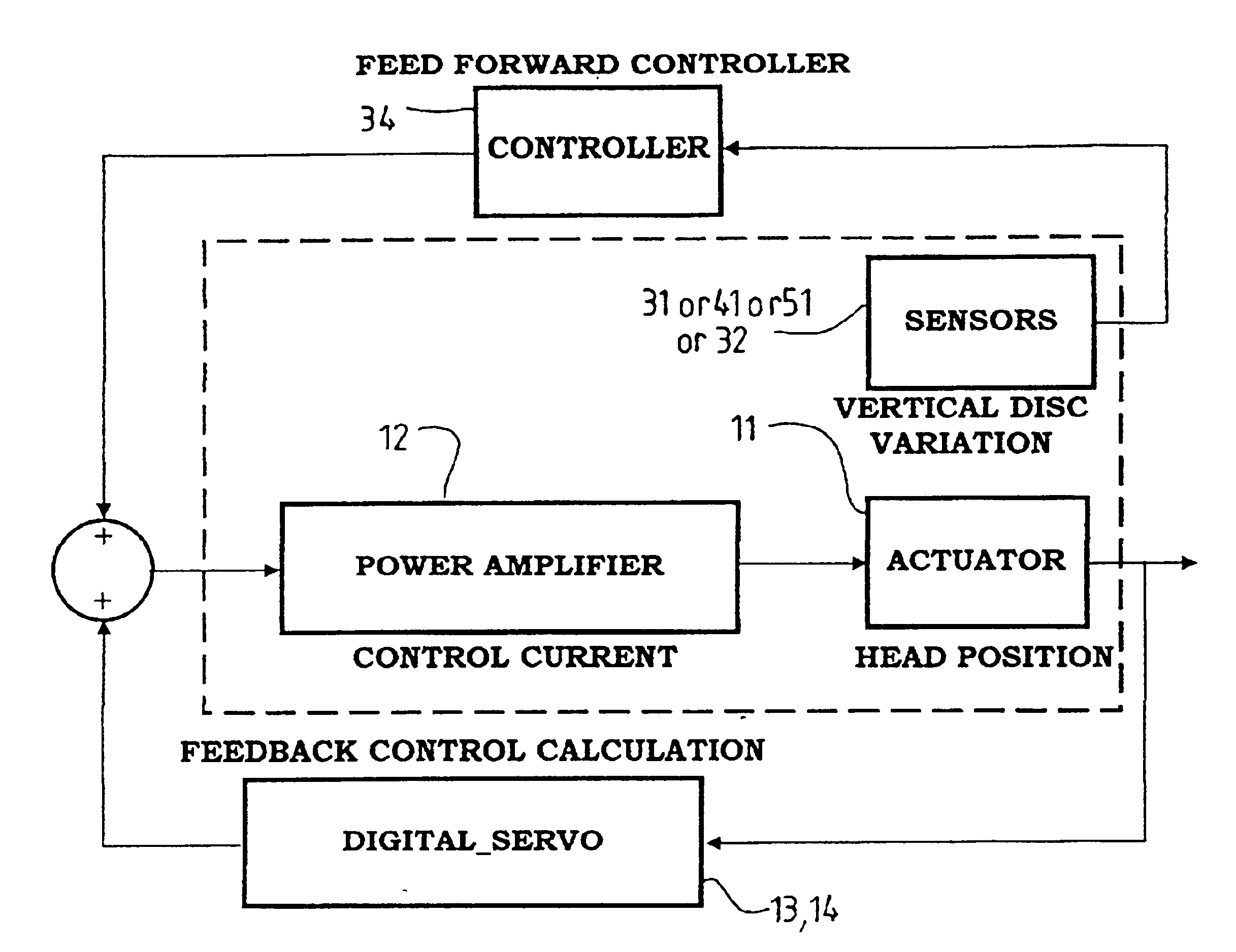
[0036]It will be appreciated that the feed forward control configurations for different types of sensor arrangements may be substantially the same, although particular parameters will typically be different. The output of the means for detecting, such as resistance variations or accelerometer outputs, can be transformed into a control signal to be used by a servo system to move the actuator assembly in a compensatory manner, in order to cancel or counteract off-track deviation of the read / write head which may be caused by disk flutter.
[0037]The present invention provides a sensor based tracking control method and apparatus that can be easily incorporated with traditional track following controllers. Further, as the external injected signal is advantageously outside the closed-loop servo control, it will not affect the stability of the system. This avoids the difficulties involved in shaping the response of the servo loop at frequencies close to the cross-over frequency. Thus, the requirements on the servo loop bandwidth and consequently the requirements on the actuator, or dual-stage actuator, are less stringent.

Problems solved by technology

Typically, two types of narrow bandwidth mechanical disturbances are present in an HDD servo system, both of which contribute to the R / W head deviating off-track.
Although such methods of adaptive control can seem very complicated, during implementation of such methods, one can simply record (“calibrate”) the necessary control action corresponding to each location of the disk surface and play back the recorded signal to correct the control error due to RRO.
The second type of narrow bandwidth mechanical disturbance which can be present in a HDD servo control system, arises due to disk vibration and thus is asynchronous with the disk spinning.
Such optimization of the mechanical system will tend to attenuate disk vibration caused by disk fluttering.
Consequently, the ability to insert a narrow bandwidth filter at a few hundred hertz is limited by the stability of the closed-loop of the servo system.
Furthermore, the settling process is very slow when narrow band filters are used in the loop.
As a matter of fact, reducing the prolonged settling process was one of the key issues pointed out in Sri-Jayantha's paper.
The error rejection improvement is thus limited to a few dB.
This approach however, does not help improving the tracking accuracy.

Method used


Image

  • Active control system and method for reducing disk fluttering induced track misregistrations
  • Active control system and method for reducing disk fluttering induced track misregistrations
  • Active control system and method for reducing disk fluttering induced track misregistrations

Examples


Embodiment Construction

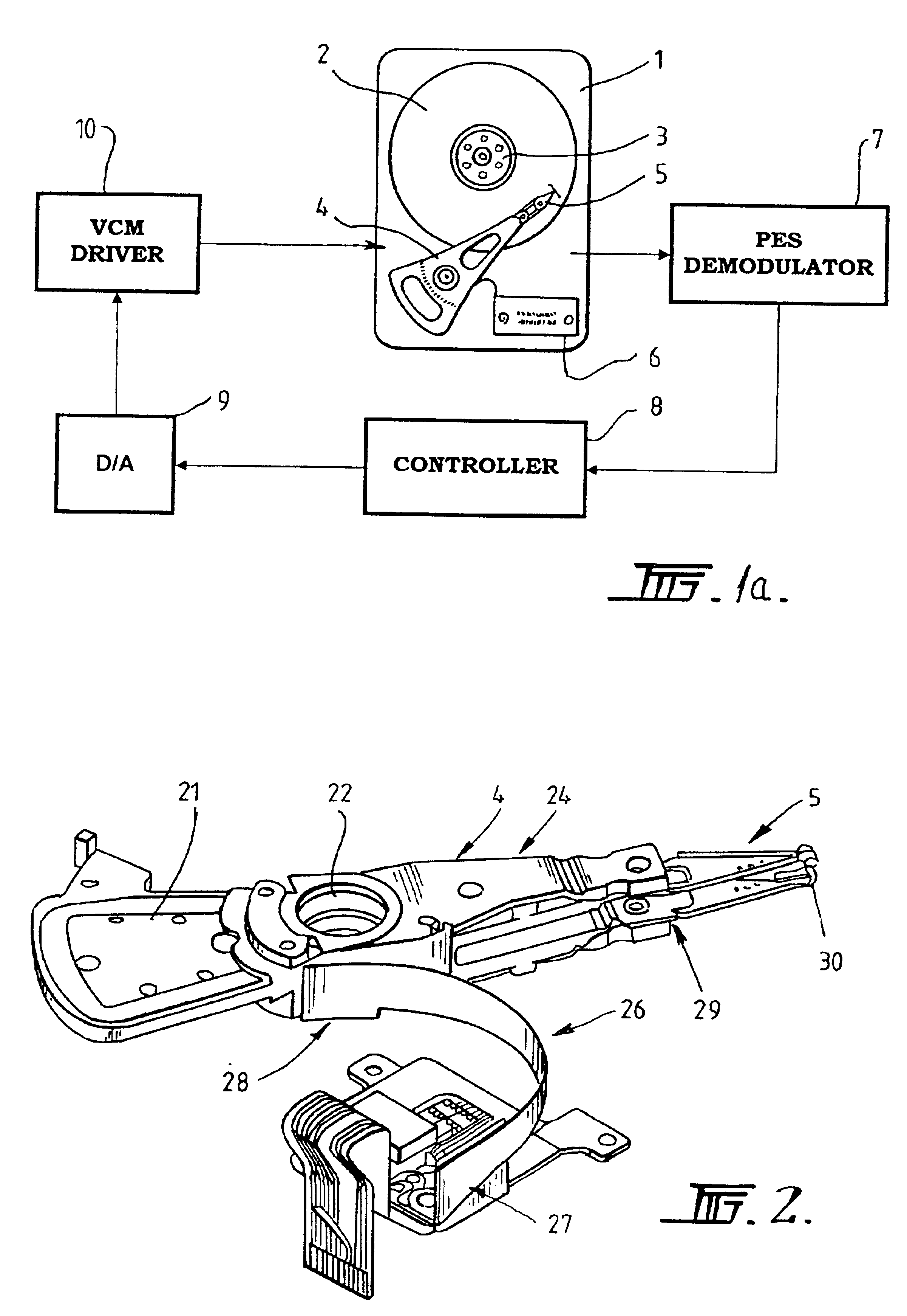
[0049]Referring now to FIG. 1a, there is illustrated a disk drive (1) with a number of rotatable disks (2) which may be turned by a spindle motor (3). A rotary actuator (4) moves a suspension (5) supporting a R / W head, which accesses concentric data tracks on the disk surface. The signal picked up by the R / W head is amplified and filtered. The signal is passed to a circuit (7) that detects the position error signal (PES) and track number. The R / W head can, for example, be a magnetoresistive (MR) head or a giant magnetoresistive (GMR) head, and thus, in such embodiments the PES obtained from the PES demodulator (7) is normally linearized. The linearized PES signal and the track numbers are passed to a servo controller (8) which calculates a required control signal in digital format and outputs the control signal to a voice coil motor (VCM) driving circuit (10) via a digital to analog converter (DAC) (9). Depending on the servo loop bandwidth and access speed requirements, a secondary...


PUM

PropertyMeasurementUnit
frequenciesaaaaaaaaaa

Abstract

The present invention relates to controlling an actuator for positioning a read / write head in storage devices such as disk drives. More specifically, the invention relates to using a sensor to detect the disk vibration amplitude perpendicular to the disk surface, and using feed forward control to cancel or counteract the tendency of the read / write head to deviate off-track due to disk vibration. Various approaches are proposed to detect the disk vertical vibration.

Description

FIELD OF THE INVENTION[0001]The present invention relates to controlling head positioning actuators in storage devices such as disk drives via feed forward control, to reduce or counteract disk flutter induced off-track deviation of the read write head. More specifically, the invention relates to employing sensors to detect the magnetic disk vibration perpendicular to the disk surface, and using feed forward control to cancel or counteract the off-track deviation of the head caused by disk vibration. Various approaches for detecting the disk vertical vibration are proposed. A control system structure is also proposed.BACKGROUND OF THE INVENTION[0002]A typical magnetic disc drive (HDD) includes one or more read / write (R / W) heads for reading data from or writing data to one or more discs mounted on a spindle motor. The data is stored in generally concentric tracks on the disc surface. During operation of the drive, the read / write heads are positioned at selected radial locations while...

Claims


Application Information

Patent Timeline
Patent Type & Authority Patents(United States)
IPC IPC(8): G11B21/10G11B5/55G11B21/21
CPCG11B21/106G11B5/5526
Inventor GUO, GUOXIAOZHANG, JINGLIANGHE, ZHIMINONG, ENG HONG
Owner AGENCY FOR SCI TECH & RES
Learn More