Image forming apparatus

Inactive Publication Date: 2005-12-13
CANON KK
View PDF9 Cites 15 Cited by
  • Summary
  • Abstract
  • Description
  • Claims
  • Application Information

AI Technical Summary

Benefits of technology

[0028]It is an object of the present invention to provide an image forming apparatus capable of fo

Problems solved by technology

However, the adoption of such a developing blade method using the layer regulating members such as the elastic blade and the metal blade easily causes the deterioration of the toner owing to the stress upon the passage of the developing blade and the generation of much frictional heat, and consequently prevents the co

Method used


Image

  • Image forming apparatus
  • Image forming apparatus
  • Image forming apparatus

Examples


embodiment 1

[Embodiment 1]

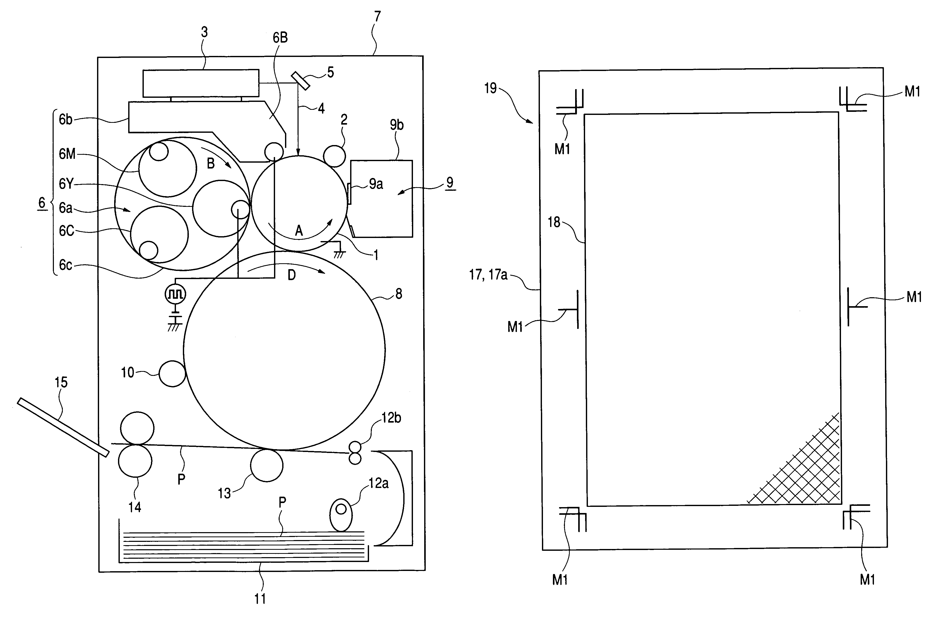
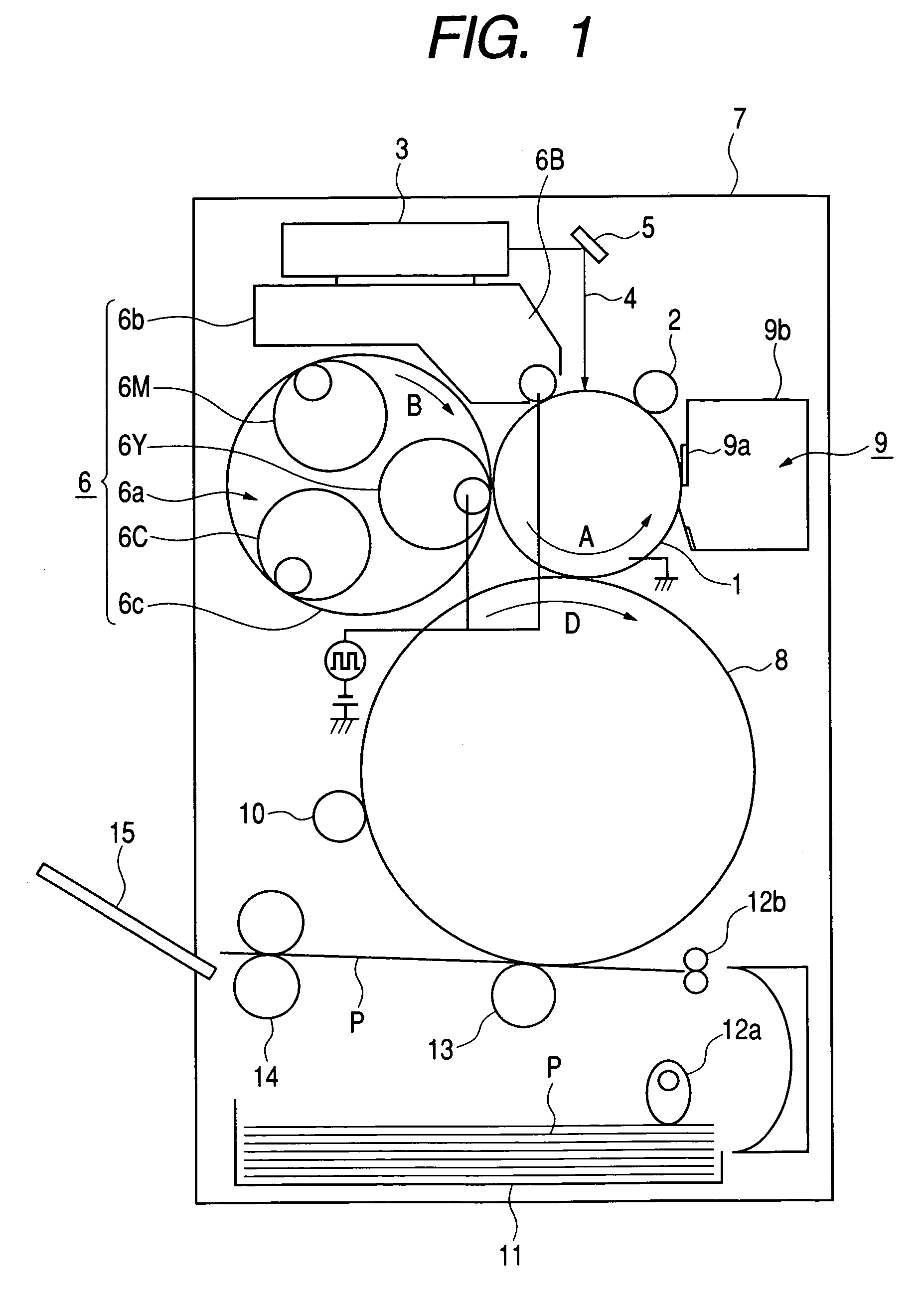
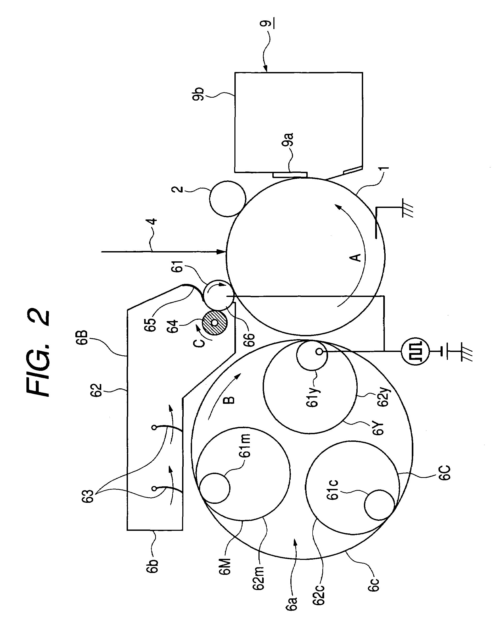
[0037]FIGS. 1 and 2 will be referred to while an image forming apparatus 7 according to a first embodiment (Embodiment 1) of the present invention is described. Incidentally, FIG. 1 is a schematic structural view showing the whole of the image forming apparatus 7 of the present embodiment. FIG. 2 is a schematic cross sectional view showing an arrangement of an image bearing member, on the surface of which an image is formed, and image forming means disposed around the image bearing member.

[0038]In the present embodiment, the electrophotographic image forming apparatus 7 is used as an image forming apparatus. As shown in FIG. 1, as an image bearing member, a photosensitive drum 1 being an electrophotographic photosensitive member composed of a cylindrical base and a photoconductive layer formed thereon, which is made of an organic photoconductor, is attached rotatably at a predetermined circumferential speed in the direction of an arrow A. Incidentally, in the present e...

embodiment 2

[Embodiment 2]

[0084]The present invention can be applied to the image forming apparatus having the configuration other than that of Embodiment 1 as long as the image forming apparatus include a plurality of developing devices.

[0085]A color image forming apparatus 7′ of the present embodiment is one shown in FIG. 4. The color image forming apparatus 7′ is provide with a digital color image printer portion (hereinafter referred to as “printer portion”) I at the lower part, and a digital color image reader portion (hereinafter referred to as “reader portion”) II at the upper part. The color image forming apparatus 7′ forms an image on a recording material P with the printer portion I on the basis of the image of a manuscript 30 read with the reader portion II.

[0086]The printer portion I includes a photosensitive drum 1 as an image bearing member to be driven to rotate in the direction of an arrow R1. Around the photosensitive drum 1, a primary charger (charging means) 2, exposure means...


PUM


Abstract

An image forming apparatus capable of preventing the increase of the size thereof by having a lengthened developer bearing member is provided with regard to an image forming apparatus capable of printing a registration mark (dragonfly) on a large sheet of recording paper for producing an art work in case of the use of a formed image as a printing manuscript. The length of the lengthwise direction of a developer bearing member provided in at least one developing device among the developing devices provided in the image forming apparatus is longer than those of the developer bearing members of the other developing devices.

Description

BACKGROUND OF THE INVENTION[0001]1. Field of the Invention[0002]The present invention relates to an image forming apparatus using an electrophotographic process or an electrostatic recording process, and more particularly to an image forming apparatus such as a copying machine, a printer, a facsimile machine and a composite machine including a plurality of functions of the above-mentioned apparatus.[0003]2. Description of Related Art[0004]In an image forming apparatus for forming a color image by superposing a plurality of toner images each having different colors, for example as shown in FIG. 5, an image forming apparatus 70 using an intermediate transfer member 54 has been proposed conventionally with an object of obtaining a color image having no color shifts.[0005]In the image forming apparatus 70, charging means 51, exposure means 52 and developing means 53 are disposed around an electrophotographic photosensitive member 50 as an image bearing member, and a developer image (ton...

Claims


Application Information

Patent Timeline
IPC IPC(8): G03G15/01G03G15/08G03G15/36
CPCG03G15/0152G03G15/0121G03G15/0173G03G2215/0161G03G15/0163
Inventor BESSHO, YUJIMASUDA, KOJIISHIDA, YUSUKE
Owner CANON KK
Why Eureka
Try Eureka