Synthetic resin pallet

a technology of synthetic resin and pallet, which is applied in the direction of packaging, transportation and packaging, containers, etc., can solve the problems of obstructing loading work, breaking the articles of the underlying pallet, and load collapsing, so as to achieve the effect of high conveying stability

Inactive Publication Date: 2005-12-20
DAINIPPON INK & CHEM INC
View PDF16 Cites 44 Cited by
  • Summary
  • Abstract
  • Description
  • Claims
  • Application Information

AI Technical Summary

Benefits of technology

[0009]It is a first object of the present invention to provide a synthetic resin pallet having a sufficient strength. It is a second object of this invention to provide a synthetic resin pallet which has sufficient fitting force to prevent plate-like link portions from inadvertently coming off during loading even when the pallet on a floor is shifted back and forth and right and left with the plate-like link portions attached to the leg portions of the pallet body.

Problems solved by technology

In the case where such synthetic resin pallets having articles placed thereon were stacked one on another, the leg portions of a synthetic resin pallet would hit the articles of the underlying pallet, thus breaking the articles of the underlying pallet.
When such synthetic resin pallets having articles placed thereon were moved on a roller conveyor, undesirable vibration could occur, thus causing load collapsing.
With the engaging mechanism that secures the plate-like link portions only with the engagement portions provided on the bottom surfaces of the leg portions, when a loading worker, however, moved the pallet dragging on the floor, shearing force would be applied to the fitting section depending on the moving direction, so that the plate-like link portions would often come off carelessly, thus obstructing the loading work, which was inconvenient.
Even this structure does not provide a sufficient strength to handle heavy articles.

Method used


Image

  • Synthetic resin pallet
  • Synthetic resin pallet
  • Synthetic resin pallet

Examples


second embodiment

[0050]FIGS. 7 through 9 illustrate a second embodiment of this invention. In this second embodiment, to ensure easier pickup of stacked pallets, ribs 13 extending upward and downward are formed inside and / or outside the sides of the small leg portions 3.

[0051]It is preferable that at least one rib 13 be provided on the inside of the small leg portions 3 of an underlying pallet which the bottom portions of the small leg portions 3 of an overlying pallet contact, with the pallets piled up. The formation of such ribs 13 makes it easier to separate stacked pallets.

[0052]Those ribs 13 may be formed on both of the inside surface and the outside surface as well as only on the inside surface or only on the outside surface. When one rib 13 is formed on one side of the small leg portion 3, it is preferable that the rib 13 be so formed as to be positioned approximately the center portion of the side surface. When a plurality of ribs 13 are formed on one side, it is preferable that the ribs 13 ...

third embodiment

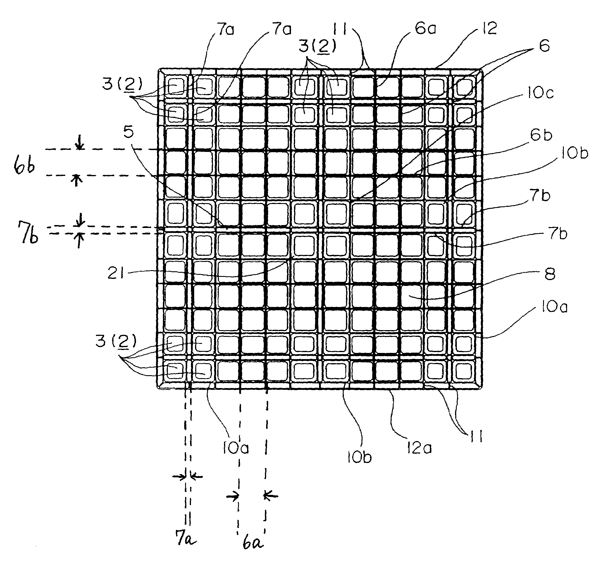
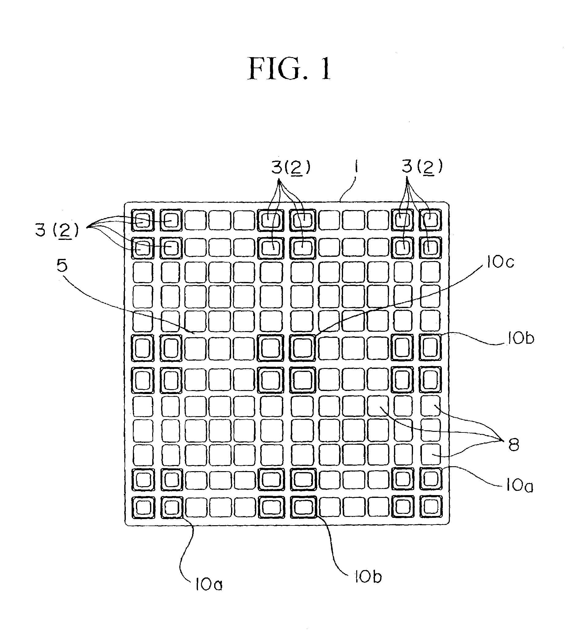
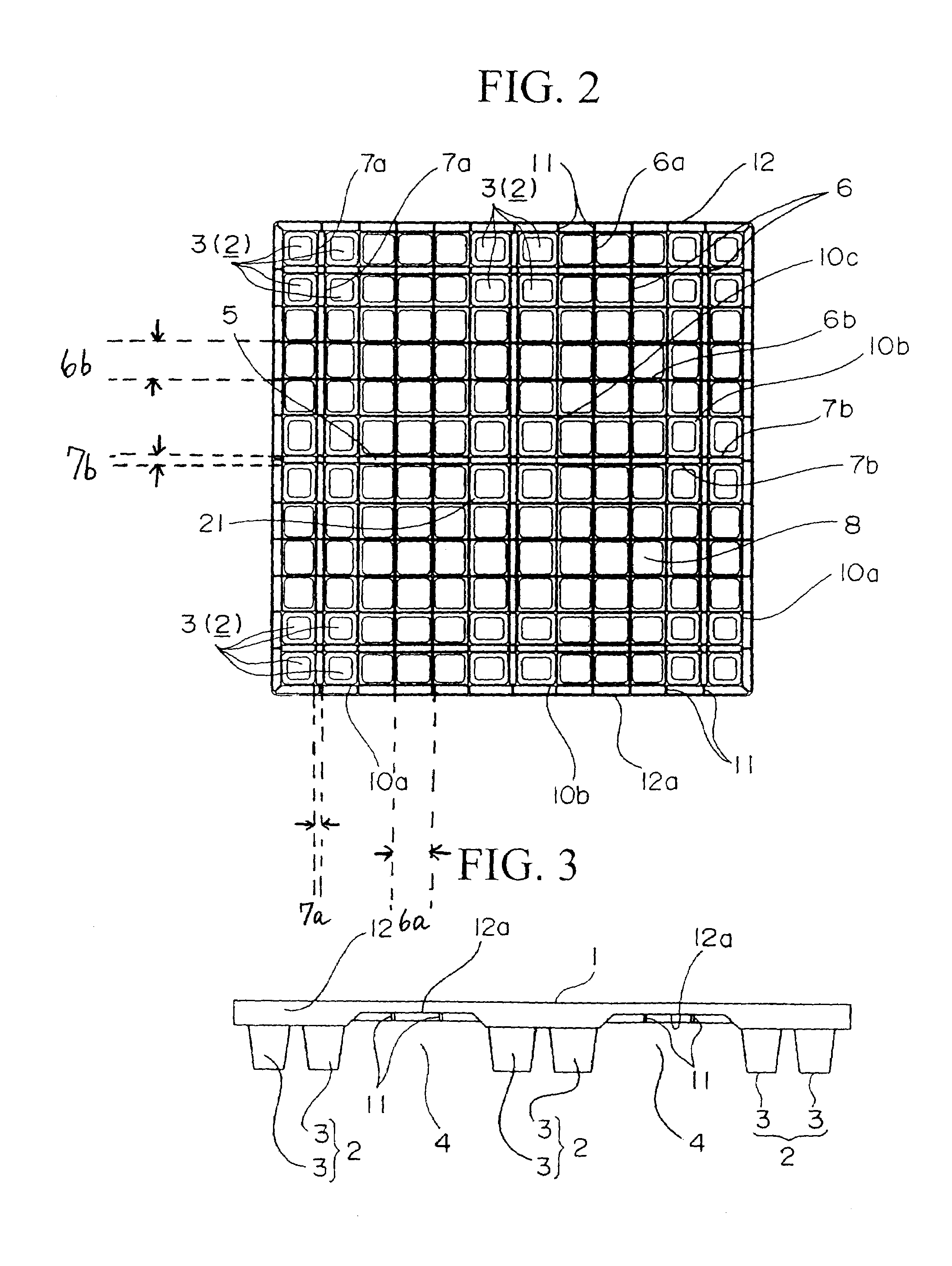
[0056]FIGS. 10 through 15 illustrate a third embodiment of a synthetic resin pallet according to this invention, and same reference numerals are given to those portions which are common to the previous embodiments to omit their description. The synthetic resin pallet of this embodiment comprises a pallet body 21 and plate-like link portions 20 of a synthetic resin which are detachably attached to the bottoms of the leg portions 2 of the pallet body 21. FIGS. 10 and 11 are a plan view and a bottom view of this synthetic resin pallet, FIG. 12 is a partially perspective view showing the plate-like link portion 20, FIG. 13 is an enlarged cross-sectional view along the line C-C in FIG. 10, FIG. 14 is a front view of the synthetic resin pallet and FIG. 15 is a cross-sectional view of the synthetic resin pallet.

[0057]In the pallet body 21, an engagement hole 22 of an elliptical shape or the like and a bank portion 23 protruding upward along the upper opening edge of the engagement hole 22 ...


PUM


Abstract

This synthetic resin pallet has a load portion 1 and a plurality of leg portions 2 protruding downward from the load portion 1 with fork inserting portions 4 provided between the leg portions 2. The load portion 1 comprises a horizontal plate portion and a grating portion 6 formed by intersection of a plurality of vertical ribs 6a, 7a and a plurality of horizontal ribs 6b, 7b, provided at a bottom of the horizontal plate portion. The leg portions 2 are so formed as to protrude downward from a lower end of the grating portion 6. Each of the leg portions 2 comprises a plurality of small leg portions 3 that are separated by a plurality of parallel vertical ribs 7a and / or a plurality of parallel horizontal ribs 7b. Engagement holes 22 are formed in the small leg portions 3 and plate-like link portions 20 are attached by fitting engagement portions 24 in the engagement holes. Recesses in which the small leg portions 3 are to be fitted are formed in the plate-like link portions 20.

Description

TECHNICAL FIELD[0001]The present invention relates to a synthetic resin pallet that is used in transporting various articles.BACKGROUND ART[0002]Conventionally, a synthetic resin pallet that has a load portion on which articles are loaded and a plurality of leg portions extending downward from the load portion with fork inserting portions provided between the leg portions is used at the time of transporting various articles.[0003]In the case where such synthetic resin pallets having articles placed thereon were stacked one on another, the leg portions of a synthetic resin pallet would hit the articles of the underlying pallet, thus breaking the articles of the underlying pallet.[0004]When such synthetic resin pallets having articles placed thereon were moved on a roller conveyor, undesirable vibration could occur, thus causing load collapsing.[0005]Japanese Patent Application, First Publication No. Hei 11-236040 has proposed a synthetic resin pallet that comprises a synthetic resin ...

Claims


Application Information

Patent Timeline
Patent Type & Authority Patents(United States)
IPC IPC(8): B65D19/00
CPCB65D19/0018B65D19/0026B65D2519/00034B65D2519/00069B65D2519/00268B65D2519/00273B65D2519/00288B65D2519/00308B65D2519/00318B65D2519/00323B65D2519/00333B65D2519/00338B65D2519/00407B65D2519/00412B65D2519/00557B65D2519/00567B65D2519/0094B65D19/40
Inventor SUGIHARA, JUNROKUROSAWA, KIYOSHIDOBASHI, TOMOYUKIYAMAMOTO, SOSHI
Owner DAINIPPON INK & CHEM INC
Why Eureka
Try Eureka