Free flow valve and element

a free flow valve and element technology, applied in the direction of diaphragm valves, valve arrangements, engine diaphragms, etc., can solve the problems of reducing the tensile force of the diaphragm valve. , to achieve the effect of reducing or eliminating the tensile force during operation

Active Publication Date: 2005-12-20
PARKER INTANGIBLES LLC
View PDF5 Cites 22 Cited by
  • Summary
  • Abstract
  • Description
  • Claims
  • Application Information

AI Technical Summary

Benefits of technology

[0014]A principal advantage of the invention resides in the user's ability to remove the entire insert, which includes all wetted surfaces. Another advantage of the present invention is the integral nature of the gasket to the tri-clamp ends of the insert for materials, which eliminates the need for a gasket in the connection points. Further, extra length of the tubing insert reduces or eliminates tensile force during operation of the valve when the insert is axially compressed to fit the specialized backup cups into the grooves of the top and bottom halves of the valve.
resides in the user's ability to remove the entire insert, which includes all wetted surfaces. Another advantage of the present invention is the integral nature of the gasket to the tri-clamp ends of the insert for materials, which eliminates the need for a gasket in the connection points. Further, extra length of the tubing insert reduces or eliminates tensile force during operation of the valve when the insert is axially compressed to fit the specialized backup cups into the grooves of the top and bottom halves of the valve.

Problems solved by technology

However, diaphragm valves maintain significant drawbacks in these areas that can be improved upon.
For example, diaphragm valves have to be mounted in a specific configuration to permit drainage, which makes them installation sensitive.
Second, the diaphragm in diaphragm valves creates a large sealing area which has potential to trap bacteria or leak.
An issue with pinch valves that concerns individuals in the aforementioned industries is the reliability of the tubing element or insert.
Particularly, closing the valve places the insert tubing under tensile force (ie, repeated flexing or cycling) which wears the insert making it unsafe for use.
Hand cleaning results in decreased productivity and potential introduction of foreign agents into the valve and / or process stream.
Another problem with existing pinch valves is that the flexible tubing element is not manufactured from a high-purity material.
Current materials are often toxic elastomers manufactured in unsanitary environments, potentially contaminating products.
The drawback of current tri-clamp designs is that a gasket is required between the valve and the connecting surface.

Method used


Image

  • Free flow valve and element
  • Free flow valve and element
  • Free flow valve and element

Examples


Embodiment Construction

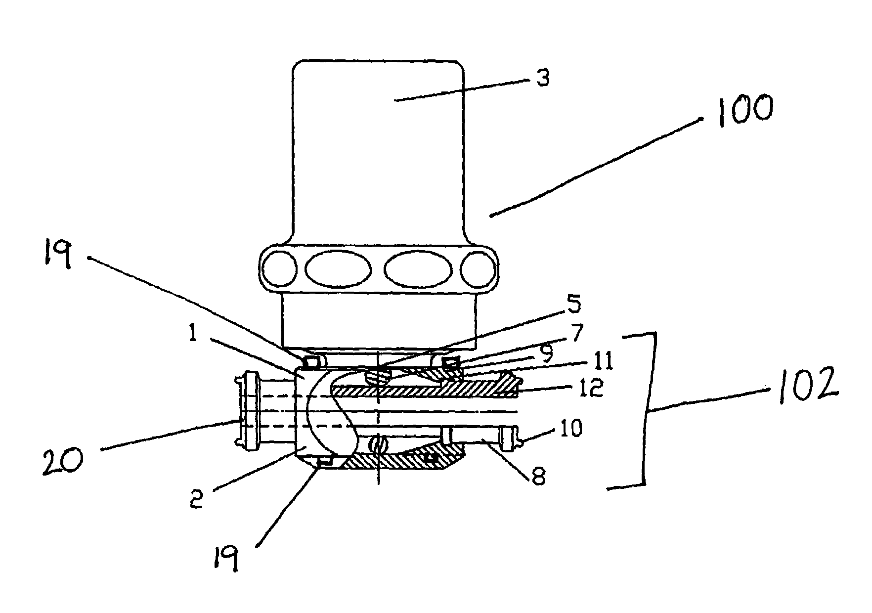
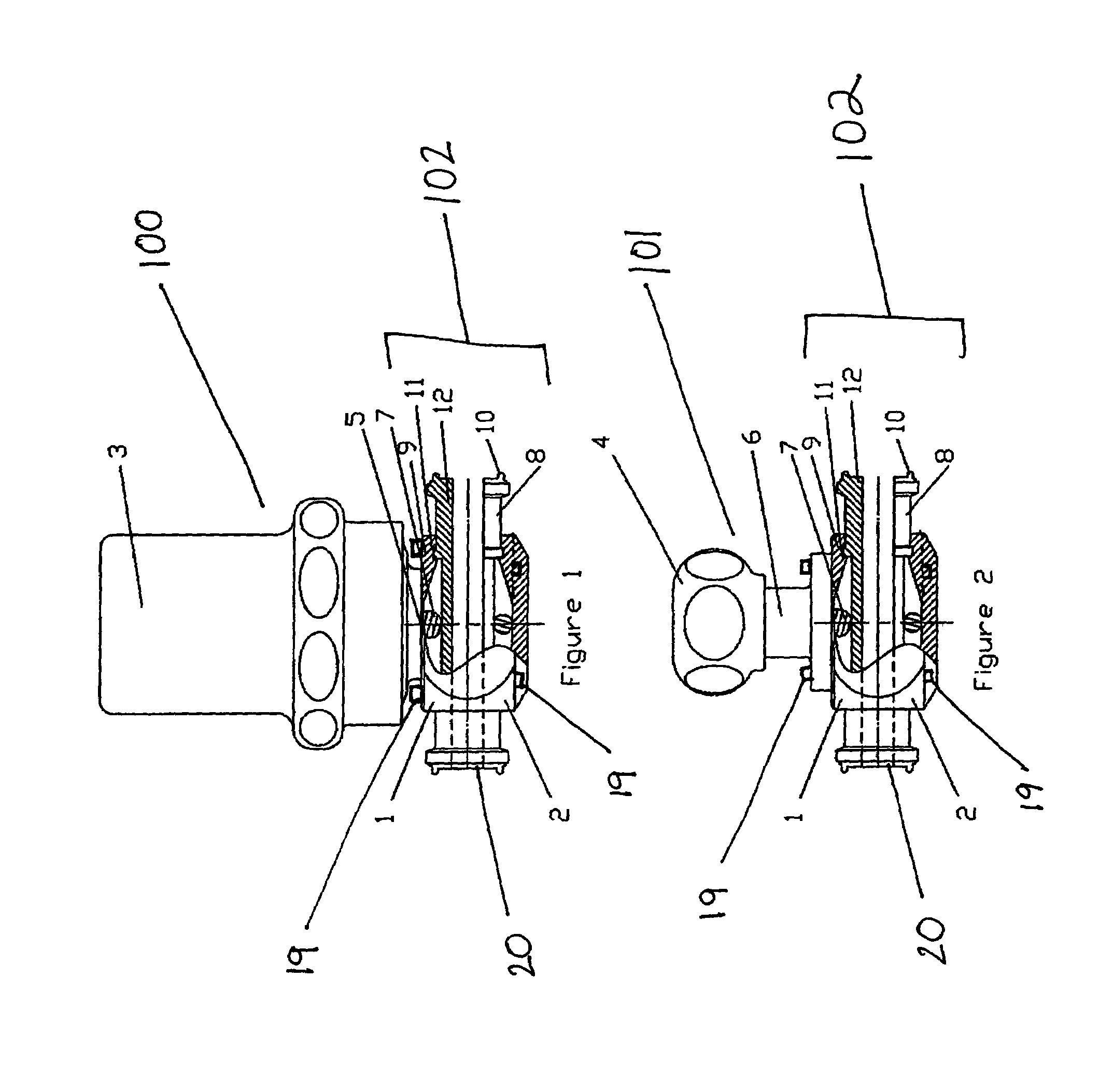
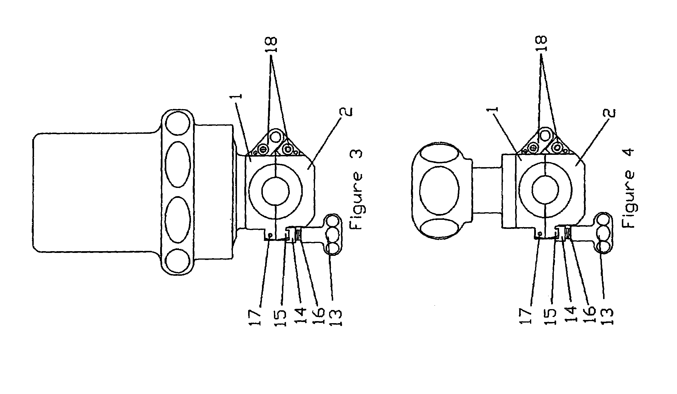
[0022]Referring to the attached Figures, the present invention provides a novel straight-through bore flow axis valve and a silicone- or PTFE-composite removable tubing element. FIG. 1 illustrates the valve with a pneumatic actuator 100 that requires air pressure in order to operate the valve. FIG. 2 illustrates the valve with a manual actuator 101, which allows the valve to be operated by human hand. The top and bottom portions 1, 2 of the valve casing 102 are labeled respectively in FIGS. 1 & 2.

[0023]Referring to FIG. 2, the manual version of the valve prevents the element 12 from being overcompressed by having the topworks 4 bottom out on the manual stem 6 when the actuator 101 is fully engaged (ie, completely closed off). Referring back to FIG. 1, the pneumatically actuated version of the valve accomplishes the latter by having components in the pneumatic actuator 100 bottom out when the actuator 100 is fully engaged or closed. Overcompression of the element 12 is prevented in b...


PUM


Abstract

A gasketless, straight-through bore fluid flow pinch valve and flexible, removable tubing element for improved sanitary conditions in production facilities. The valve casing is joined by fittings that enable separation of the casing to remove and replace the flexible element, which includes all wetted surfaces. The fittings may be one or more hinges to permit partial separation of the valve casing, which permits the element to remain on-line while maintenance is performed on the valve. The flexible element is a silicone or PTFE-composite which is in an axially compressed state when locked into the valve by rigid, tolerance-fitted backup cups on the molded ends of the element, which increases the process life of the element.

Description

FIELD OF INVENTION[0001]The present invention pertains to the field of fluid handling and positive shutoff-type flow valves. Specifically, the invention pertains to gasketless valves with smooth, noncontaminating straight-through bore fluid flow that are used in the sanitary field of pinch valves. More specifically, the invention pertains to pinch valves that incorporate a flexible, compressible tubing element to create a smooth, noncontaminating fluid flow so that all wetted surfaces (ie, surfaces making contact with fluid) are removable and replaceable.BACKGROUND OF INVENTION[0002]In many industries, such as the food industry, biological R&D, biological pilot plants and production facilities, the handling of fluid products requires an extremely sanitary environment. Equipment designed for product contact must create nonturbulent flow to safeguard products from damage as they travel through the valve. Ideally, a smooth, reliable passageway should be provided that is completely drai...

Claims


Application Information

Patent Timeline
Patent Type & Authority Patents(United States)
IPC IPC(8): F16K7/04
CPCF16K7/04
Inventor WELCH, STEVEN D.ELBICH, ROBERT J.ZETTERSTRAND, ERIK
Owner PARKER INTANGIBLES LLC
Why Eureka
Try Eureka