Part transfer system and method

a transfer system and part technology, applied in forging presses, metal-working feeding devices, forging/pressing/hammering apparatuses, etc., can solve the problems of fluid and other residue left in the final part, and achieve the effect of reducing or eliminating second trimming operations

Inactive Publication Date: 2010-01-28
HMS PRODS
View PDF14 Cites 0 Cited by
  • Summary
  • Abstract
  • Description
  • Claims
  • Application Information

AI Technical Summary

Benefits of technology

[0008]The subject invention holds the work-piece in a vertical orientation parallel to the vertical-axis. In the hydroforming process, the work-piece is pressurized in each of the cavities of the die, and when the work-piece is removed from the cavity, the fluid along with any residue is flushed out of the work-piece by gravity. Similarly, in the hydrotrimming process, the work-piece can be trimmed in the die cavity and secondary trimming operations can be reduced or eliminated.

Problems solved by technology

A common problem with such hydroforming assemblies is that fluid and other residue is left in the final part following the hydroforming process.

Method used


Image

  • Part transfer system and method
  • Part transfer system and method
  • Part transfer system and method

Examples


Embodiment Construction

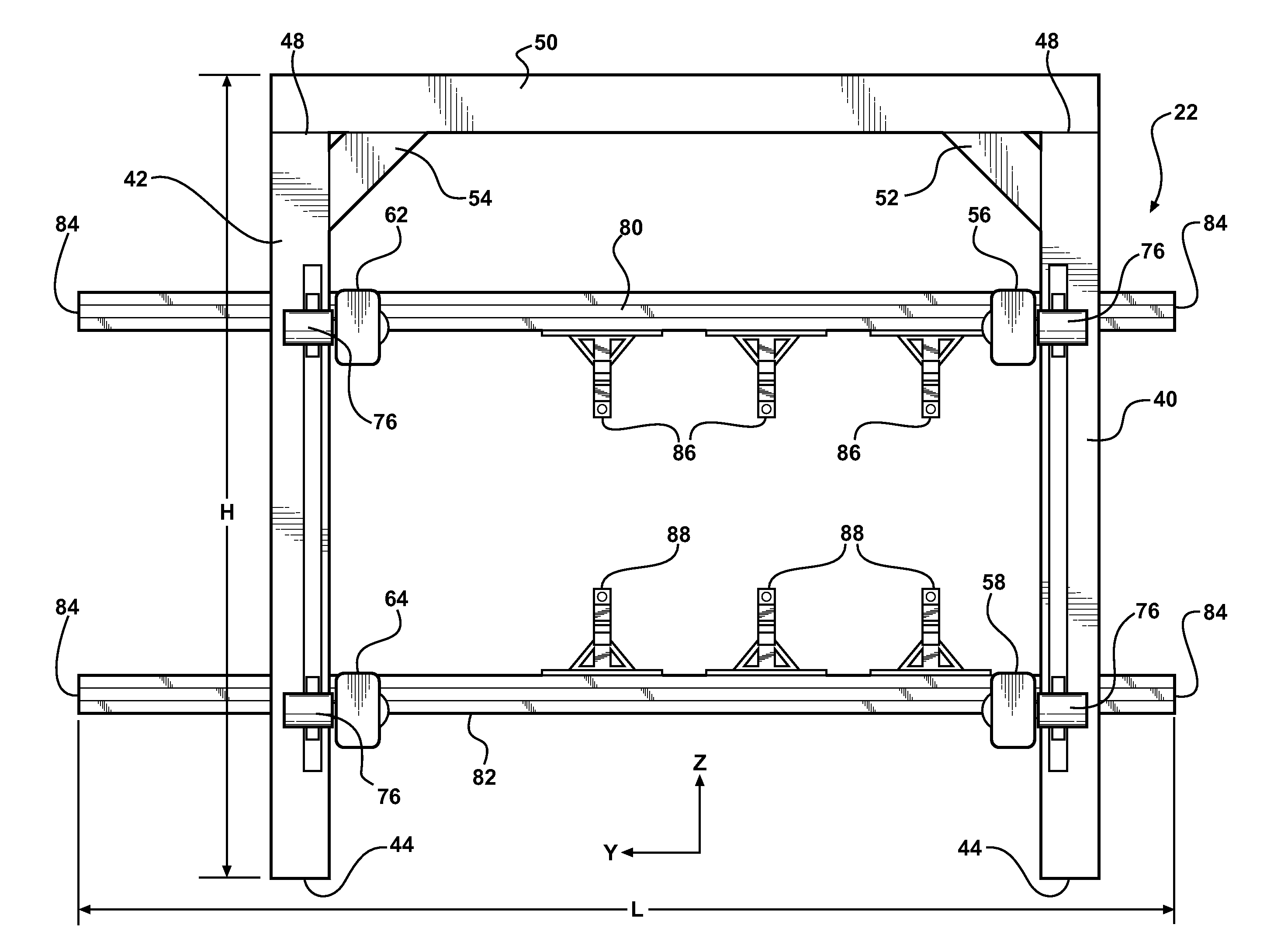
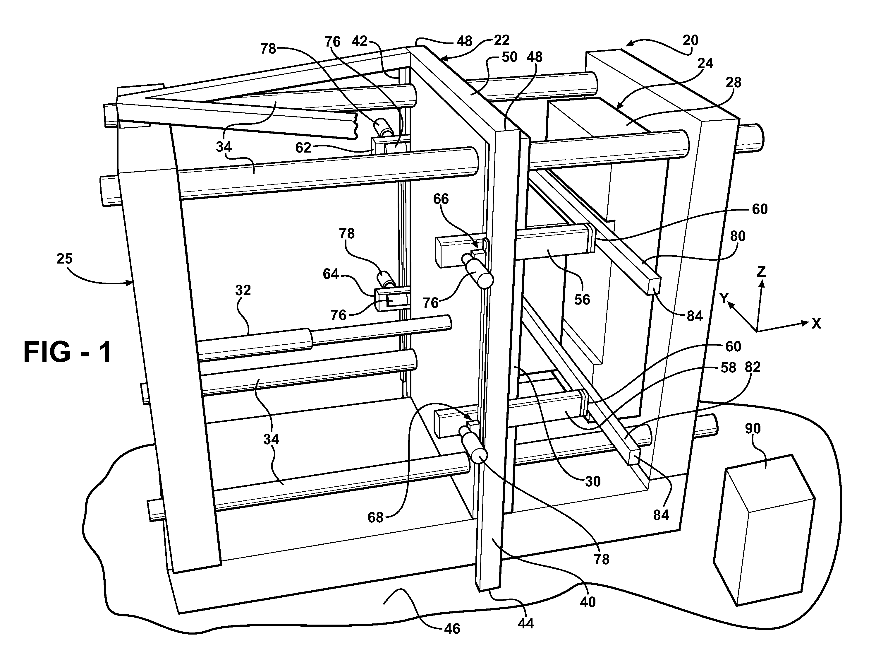
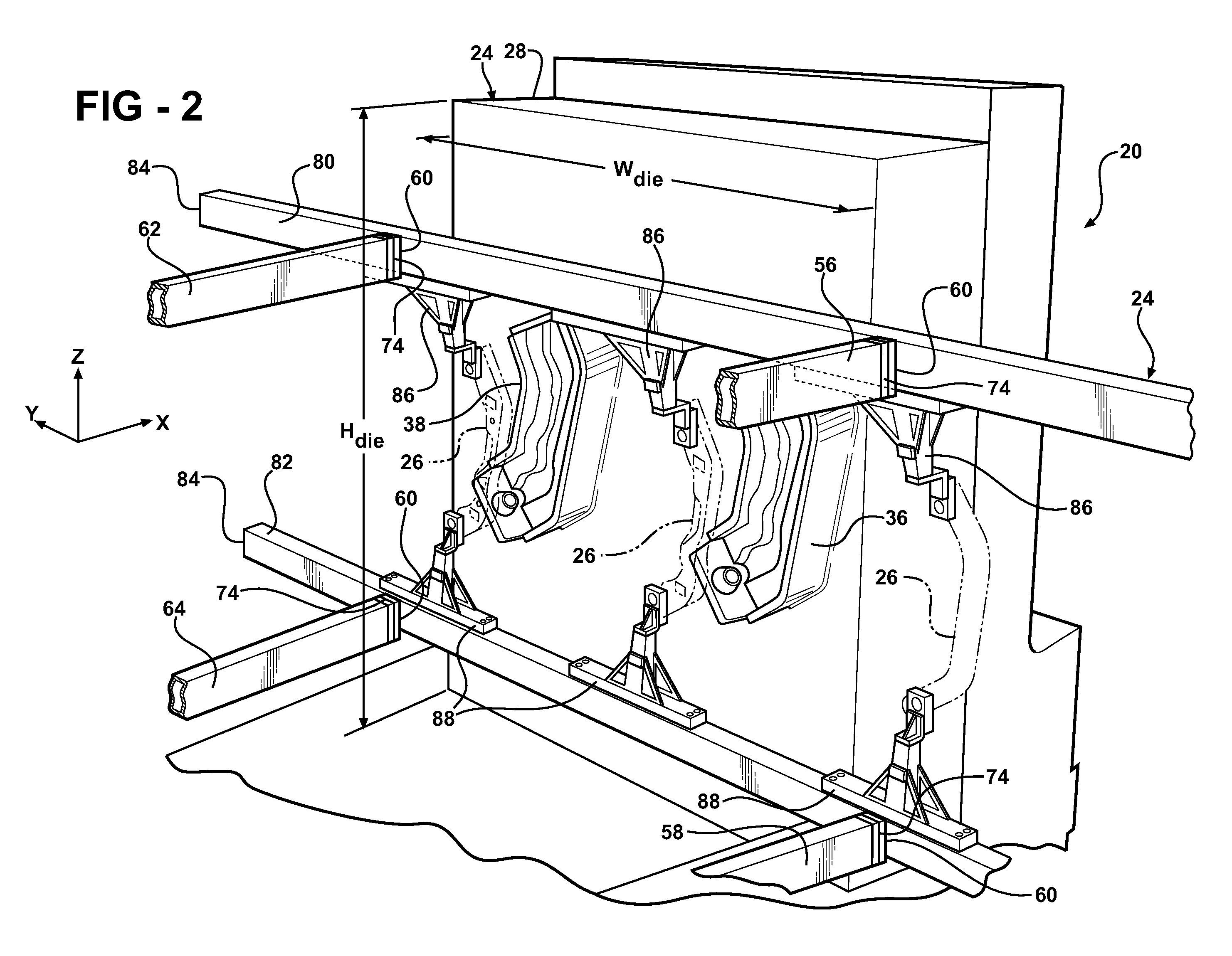
[0014]Referring to the Figures, wherein like numerals indicate corresponding parts throughout the several views, the invention is a forming machine 20 including a transfer assembly 22 having a horizontal in / out-axis X and a horizontal station-axis Y perpendicular to the in / out-axis X and a vertical-axis Z. In the exemplary embodiment, the forming machine 20 is a hydroforming machine, but it is to be appreciated that it may also be a hydrotrimming machine.

[0015]The forming machine 20, which is generally shown in FIGS. 1 and 2, includes a die 24 disposed on a press 25. The die 24 has a die width Wdie and a die height Hdie and includes a plurality of forming stations spaced from each other for successively hydroforming or hydrotrimming a work-piece 26. The press 25 and the die 24 are generally indicated in FIGS. 1 and 2, and the die 24 includes a front half 28 and a back half 30. The press 25 includes an actuator 32 for moving the front and back halves 28, 30 of the die 24 relative to ...


PUM

PropertyMeasurementUnit
lengthaaaaaaaaaa
widthaaaaaaaaaa
heightaaaaaaaaaa

Abstract

A transfer assembly (22) for moving a work-piece (26) between stations of a hydroforming and / or hydrotrimming assembly. The transfer assembly (22) includes left and right posts (40, 42) spaced from and parallel to each other and extending vertically. A left top arm (56) and a left bottom arm (58) and a right top arm (62) and a right bottom arm (64) extend in spaced and parallel relationship with each other transversely to the posts (40, 42) to distal ends (60, 84). An upper rail (80) extends between the distal ends (60, 84) of the top arms (56, 62) and a lower rail (82) extends between the distal ends (60, 84) of the bottom arms (58, 64). The rails (80, 82) each include a plurality of part grabbers (86, 88) for engaging the work-piece (26). A transfer module interconnects each arm with the associated post for moving the arms (56, 58, 62, 64) vertically up and down and for moving the arms (56, 58, 62, 64) in and out. A rail transfer module (74) interconnects each arm with the associated rail for moving the rails (80, 82) side-to-side.

Description

BACKGROUND OF THE INVENTION[0001]1. Field of the Invention[0002]The subject invention relates to a high speed vertical part transfer assembly for moving parts in a hydroforming assembly or a part trimming assembly.[0003]2. Description of the Prior Art[0004]Hydroforming generally is the use of fluid pressure to expand a blank, or a work-piece, to comply with the shape of the cavity of a die. Hydrotrimming is the process of cutting and trimming parts through the use of a hydraulic fluid. Hydroforming or hydrotrimming machines generally include a die having a cavity defining a negative mold of a final part. A work-piece is placed in the cavity of the die, and a high pressure hydraulic fluid is injected into the work-piece to cause the work-piece to conform to the shape of the negative mold.[0005]The dies of the hydroforming and hydrotrimming assemblies of the prior art are laid horizontally with two halves moveable relative to each other parallel to a vertical-axis. A common problem wi...

Claims


Application Information

Patent Timeline
Patent Type & Authority Applications(United States)
IPC IPC(8): B23P19/00
CPCB21D26/023Y10T29/534B21D43/055B21D26/035
Inventor COALSON, GLENSOFY, DAVID A.
Owner HMS PRODS
Why Eureka
Try Eureka