This helps you quickly interpret patents by identifying the three key elements:
Problems solved by technology
Method used
Benefits of technology
[0018]It is another object of this invention to provide a hydraulic puller apparatus for extracting objects anchored in the ground, including such objects that may be anchored in concrete, that can be easily and quickly set up and grip the object and operated by a single person to extract the object in a matter of minutes using a simple hand tool.
[0019]Another object of this invention is to provide a hydraulic puller apparatus that does not require a large area for extracting objects anchored in the ground including objects that may be located flush to a house or garage wall and to easy replace just one post in a fence.
[0020]Another object of this invention is to provide a hydraulic puller apparatus for extracting objects anchored in the ground, including such objects that may be a
Problems solved by technology
Typically, fence posts, poles, tent stakes, trees, ground rods, signposts, etc., are either hammered into the ground or set in concrete thus making removal difficult and time-consuming.
Some posts will be found to have broken off near ground level due to rot, high wind, fallen trees, auto mishaps or some other cause.
This presents a special removal problem.
Method used
Image
Click on the blue label to locate the original text in one second.
Reading with bidirectional positioning of images and text.
Examples
Example
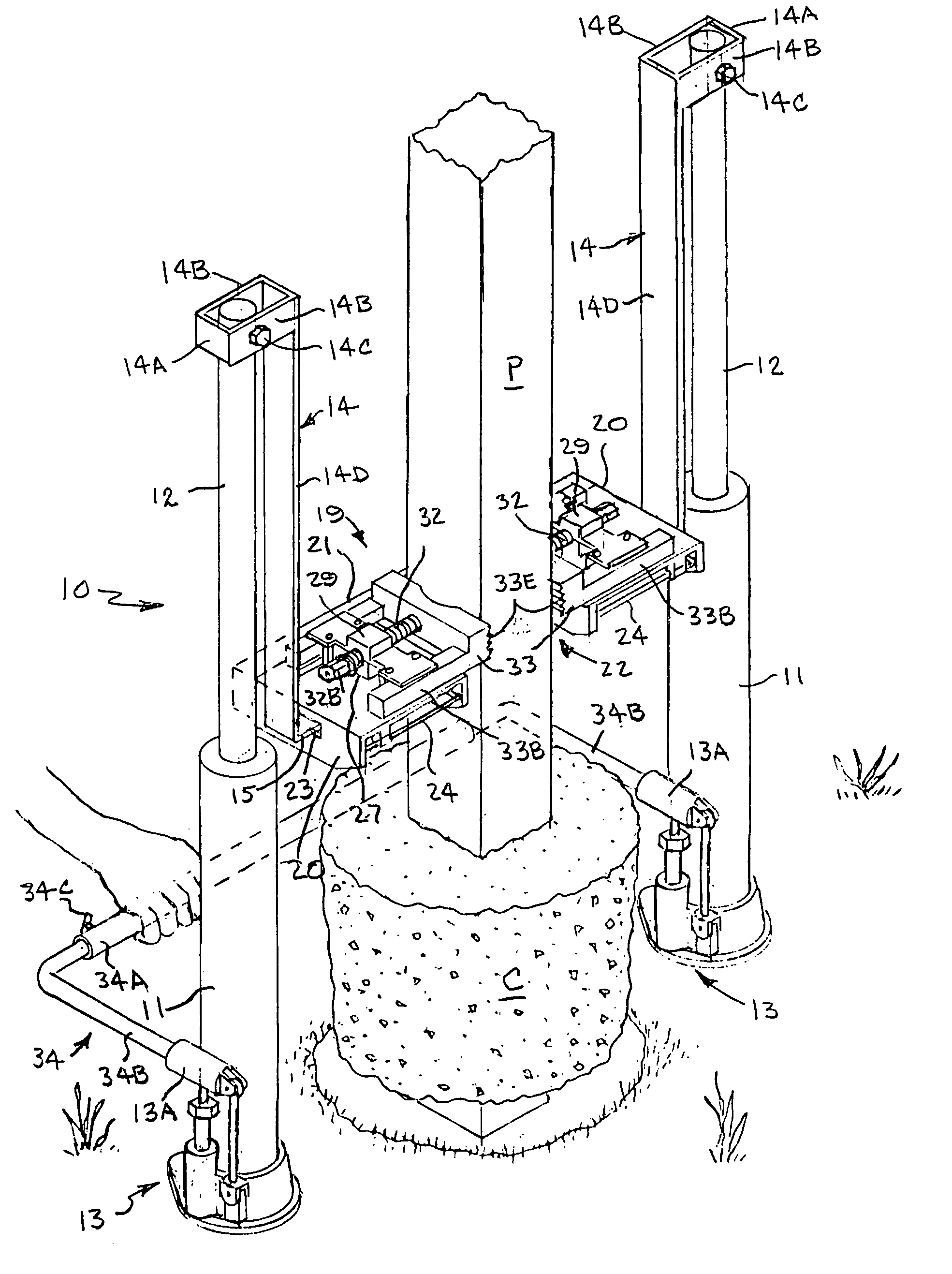
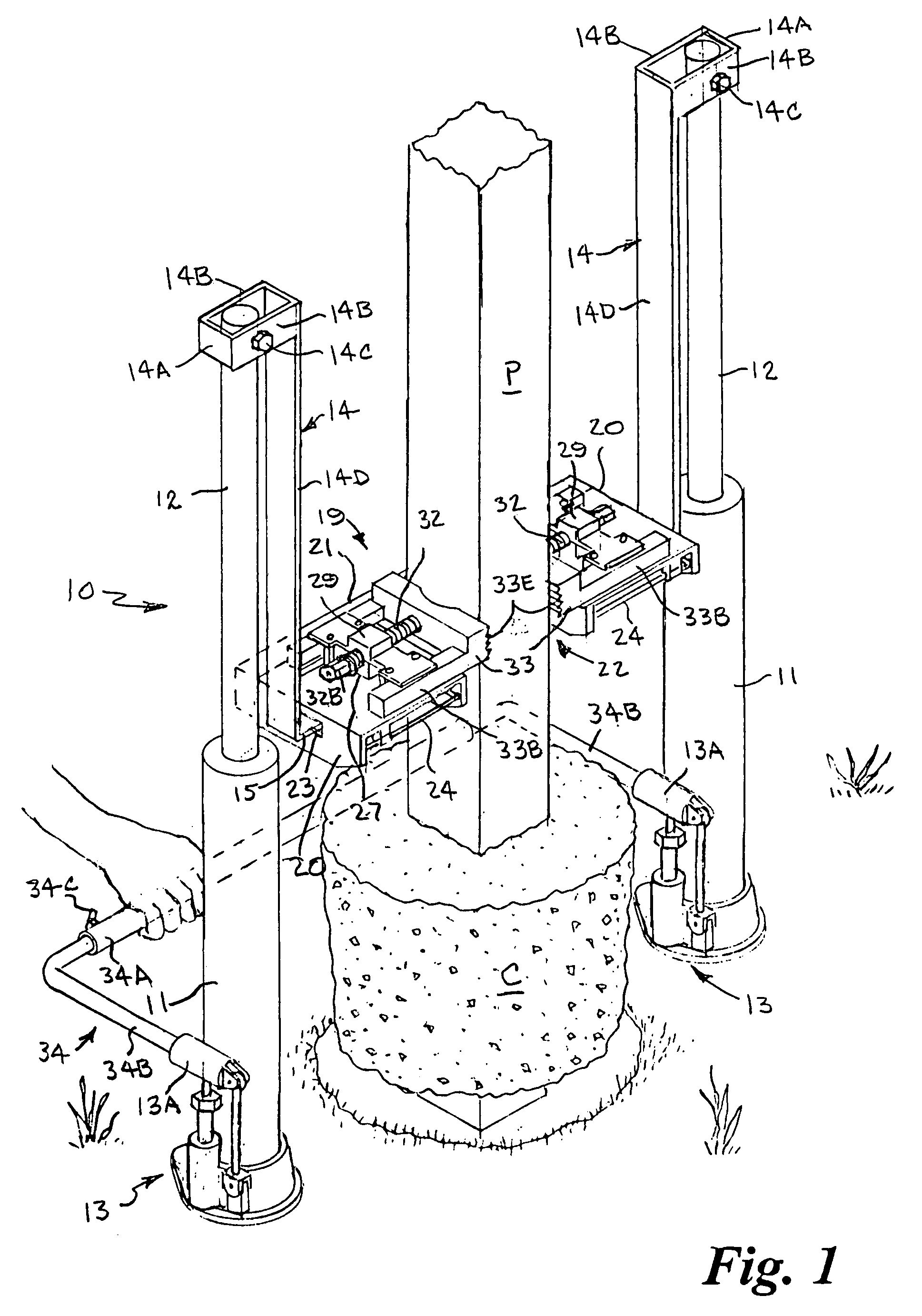
[0035]Referring to the drawings by numerals of reference, there is shown in FIGS. 1, 2 and 3, a preferred post puller apparatus 10. The post puller apparatus 10 includes a pair of modified hydraulic jack members 11, each having an extensible and retractable piston rod or ram member 12 that is raised and lowered by a pump rod and cylinder assembly 13 at its base. A lift arm 14 is pivotally connected at the top end of each ram member 12. Each lift arm 14 is a generally L-shaped member having a yoke or rectangular frame portion 14A at its upper with a pair of laterally opposed side members 14B that straddle the upper end of the respective ram member 12 and are pivotally connected thereto by a transverse bolt and nut 14C. An elongate vertical leg 14D adjoined at its upper end to one end of the frame portion 14A extends downwardly therefrom and terminates in an outwardly extending shorter horizontal leg or tongue 15.
[0036]The rectangular frame portion 14A of each lift arm 14 is sized suc...
PUM
Abstract
A hydraulic puller apparatus for extracting objects from the ground, including objects anchored in a concrete slug, includes a pair of hydraulic jacks, each having a ram with an elongate lift arm pivotally connected at an upper end thereto; and a puller head having a pair of jaw support platforms disposed on opposite sides of a generally U-shaped opening. A pair of jaws each mounted on a respective jaw support platform are moved by respective drive screws to grip opposite sides of the object. The puller head is positioned with its opening straddling a lower end of the object, the jaws are engaged on opposite sides of the object, the jacks are placed on opposite sides of the object, and the lift arms are engaged in opposed ends of the puller head. Then the jacking mechanisms of the jacks are actuated, preferably simultaneously, to extend the rams and extract the object.
Description
BACKGROUND OF THE INVENTION[0001]1. Field of the Invention[0002]This invention relates generally to post and tree pullers and, more particularly, to a hydraulic puller apparatus for extracting fence posts, small trees, tent stakes, grounding rods, mailbox posts, sign posts, and the like, including such objects that may be anchored in a concrete slug.[0003]2. Background Art[0004]Devices for removing fence posts, poles, tent stakes, trees, ground rods, signposts, etc. are well known in the art. Typically, fence posts, poles, tent stakes, trees, ground rods, signposts, etc., are either hammered into the ground or set in concrete thus making removal difficult and time-consuming. Some posts will be found to have broken off near ground level due to rot, high wind, fallen trees, auto mishaps or some other cause. This presents a special removal problem. Another problem occurs when a post being removed slips out of its concrete slug while it is still in the ground. Various removal devices an...
Claims
Application Information
Patent Timeline
Application Date:The date an application was filed.
Publication Date:The date a patent or application was officially published.
First Publication Date:The earliest publication date of a patent with the same application number.
Issue Date:Publication date of the patent grant document.
PCT Entry Date:The Entry date of PCT National Phase.
Estimated Expiry Date:The statutory expiry date of a patent right according to the Patent Law, and it is the longest term of protection that the patent right can achieve without the termination of the patent right due to other reasons(Term extension factor has been taken into account ).
Invalid Date:Actual expiry date is based on effective date or publication date of legal transaction data of invalid patent.
IPC IPC(8): E04H17/26E21B19/00
CPCE04H17/265
Inventor WOOLLEY, BRENT ALANSTARR, II, STEPHEN GARRETT