Sheet feeding device with plural sheet feeding means feeding in opposite directions to sheet post-processing system

a feeding device and post-processing system technology, applied in the direction of thin material processing, article separation, printing, etc., can solve the problems of marked reduction in the productivity of the image formation system, mismatching of the sides of the inserting sheet, and operator error setting, etc., to achieve the effect of reducing productivity

Inactive Publication Date: 2005-12-20
CANON KK
View PDF14 Cites 36 Cited by
  • Summary
  • Abstract
  • Description
  • Claims
  • Application Information

AI Technical Summary

Benefits of technology

[0007]The present invention has been made in light of the above-described problems, and accordingly, it is an object of the present invention to provide an image formation system capable of load...

Problems solved by technology

However, when the device is able to determine whether the inserting sheets are set faced up in the inserter tray 901 thereby preventing mix-ups between front and back sides of the inserting sheets due to setting errors by the operator, reversing operations of the inserting sheets need to be performed by either the sort mode, the staple sort mode, or the bookbinding mode set from the o...

Method used


Image

  • Sheet feeding device with plural sheet feeding means feeding in opposite directions to sheet post-processing system
  • Sheet feeding device with plural sheet feeding means feeding in opposite directions to sheet post-processing system
  • Sheet feeding device with plural sheet feeding means feeding in opposite directions to sheet post-processing system

Examples


first embodiment

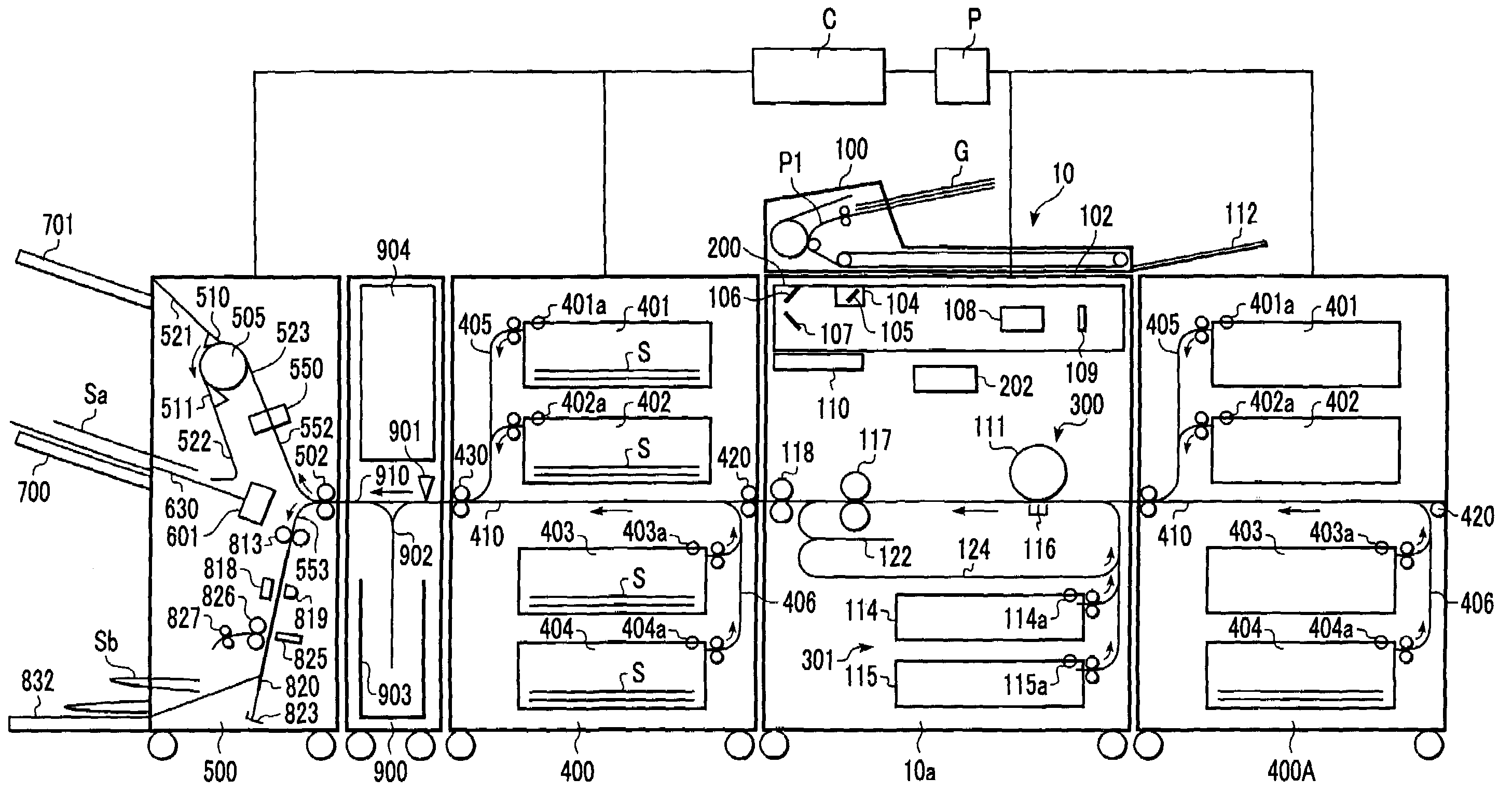
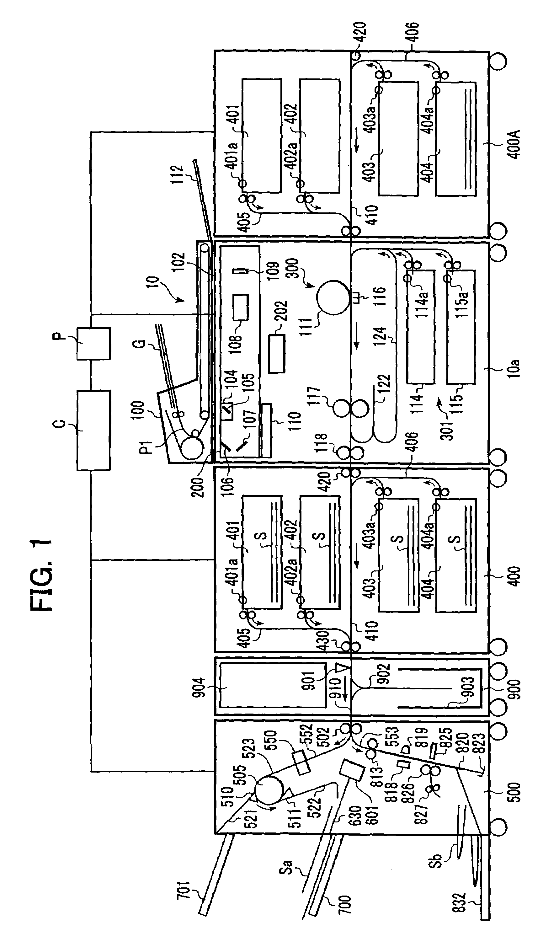
[0020]FIG. 1 is a diagram illustrating a schematic configuration of an image formation system according to a first embodiment of the present invention. In the drawing, reference numeral 10 denotes an image formation apparatus, 10a denotes an image formation apparatus main unit, 400 denotes a multiple inserter serving as a downstream side sheet feeding device disposed in parallel on the downstream side of the image formation apparatus 10, and 400A denotes a feeding deck serving as an upstream side sheet feeding device disposed in parallel on the upstream side of the image formation apparatus 10 for feeding sheets to the image formation apparatus 10. Reference numeral 500 denotes a sheet post-processing device disposed on the downstream side of the multiple inserter 400, and 900 denotes a reversing module serving as a sheet reversing device disposed between the sheet post-processing device 500 and the multiple inserter 400. Note that a sheet post-processing system according to the pre...

second embodiment

[0080]Next, description of a second embodiment of the present invention will be made.

[0081]FIG. 7 is a drawing illustrating a schematic configuration of an image formation system according to the second embodiment.

[0082]In the present embodiment, corresponding feeding units (e.g., 451a and 451b) are each disposed on opposite sides of feeding trays 451 through 454 of the multiple inserter 400 as shown in the drawing. The other components which are the same as those in the first embodiment are denoted with the same reference numerals, and description thereof will be omitted.

[0083]In the first embodiment, the feeding trays of the multiple inserter 400 to feed inserting sheets are selected based upon the selected post-processing mode. On the other hand, with the present embodiment, feeding units 451a through 454a and 451b through 454b are disposed on the both sides of the corresponding feeding trays 451 through 454, so regardless of which of the feeding trays are selected, the control u...


PUM

PropertyMeasurementUnit
Transport propertiesaaaaaaaaaa

Abstract

A feeding tray for feeding sheets from the left side thereof and a feeding tray for feeding sheets from the right side thereof are disposed on a multiple inserter, and selectively employing the feeding tray for feeding sheets from the left side thereof and the feeding tray for feeding sheets from the right side thereof allows reversal actions of sheets to be eliminated.

Description

BACKGROUND OF THE INVENTION[0001]1. Field of the Invention[0002]The present invention relates to a sheet feeding device for feeding sheets, a sheet post-processing system, and an image formation system including the sheet feeding device.[0003]2. Description of the Related Art[0004]Conventionally, there have been image formation systems which control the insertion of sheets such as book covers, inside covers, back covers following bookbinding, and so forth, at such a timing that the sheets can be inserted in a predetermined output sequence without passing through an image formation apparatus and fixing means, in order to not deteriorate quality of printing images. Such an image formation system has been disclosed in Japanese Patent Laid-Open No. 2000-211803. The image formation system described in the aforementioned Japanese Patent Laid-Open comprises a multiple inserter 900 at an upper portion of a sheet post-processing device 500 connected to an image formation apparatus 10 as show...

Claims


Application Information

Patent Timeline
IPC IPC(8): B42C19/08B65H3/44
CPCB42C19/08B65H3/44B65H2301/31B65H2402/10B65H2405/332B65H2511/414B65H2513/42B65H2220/01B65H2220/02
Inventor KAWATA, WATARU
Owner CANON KK
Why Eureka
Try Eureka