
Machine for packaging soft products

a soft product and machine technology, applied in the direction of conveyor wrapping, packaging, transit packaging, etc., can solve the problems of increasing the distance between the unit, and increasing the speed of the unit, so as to reduce the problem of speed reduction, reduce the productivity and the quality of the packaging of the product, and simplify the size change of the group

Active Publication Date: 2020-12-17
TISSUE MACHINERY
View PDF0 Cites 0 Cited by
  • Summary
  • Abstract
  • Description
  • Claims
  • Application Information

AI Technical Summary

Benefits of technology

The invention is a machine for packaging soft products that can change the size of product groups without making major modifications to the unit's structure. It also aims to reduce speed reduction issues for smaller formats without impacting productivity and quality. Additionally, it seeks to save time in modifying the configurations of carriages' teeth while maintaining safety and containment on packs of products.

Problems solved by technology

However, these modifications to the conveyor have given rise to several drawbacks.
A first drawback is due to the long length / extension of the entire ring-shaped path which makes it necessary to increase the distances between the unit and the rest of the outfeed stations.
Now, the greater the spacing (and the extension), the greater will be the speed of the power-driven units when it is necessary to package groups of products with small spacing, but if the groups have limited width and the packaging speed requested is high (in view of the length of the path) then the rotation speeds become high, to the detriment of the winding quality and reliability of the machine.
A further drawback currently present in the structure of the unit is due to the need to assemble and dismantle carriages which, according to the format needs, must be carried out manually.
Currently, in fact, the system needs a manual intervention to be able to apply or remove the carriages from the belts or chains by means of a long and laborious mechanical operation.
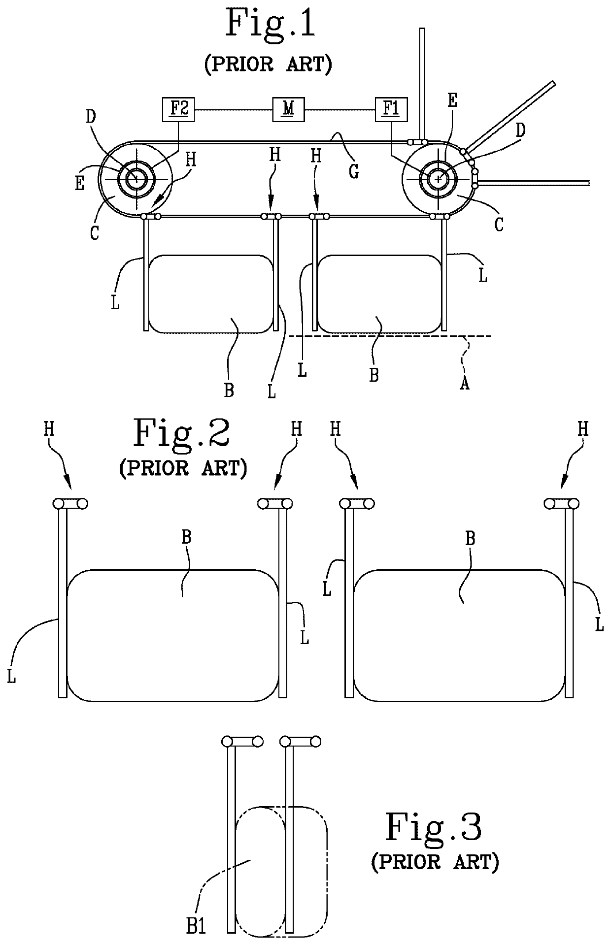
Another drawback is due to the constructional profile of each tooth, which has the shape of an upturned “L” in which, for each pair of teeth forming the containment pocket, each smaller stretch of “L” (used for connection to the carriage) faces the other one.
This configuration creates a problem which arises when the size of the formats (labelled B1 in FIG. 3) is less than the sum of the two smaller stretches of “L” (minimum spacing) and it makes it necessary to use the rotation of the pushing or containing teeth to be able to efficiently retain the products (see FIG. 3).
All these situations result in a significant waste of non-operational time on the machine.

Method used


Image

  • Machine for packaging soft products
  • Machine for packaging soft products
  • Machine for packaging soft products

Examples


Embodiment Construction

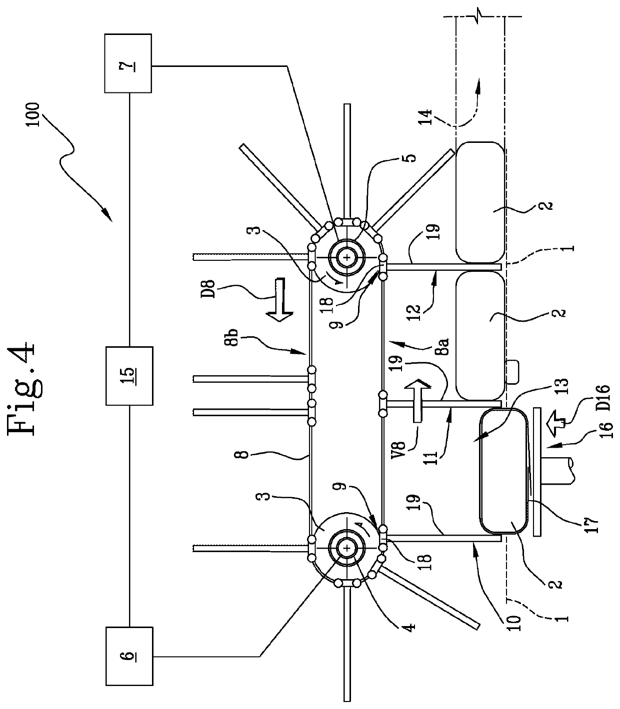
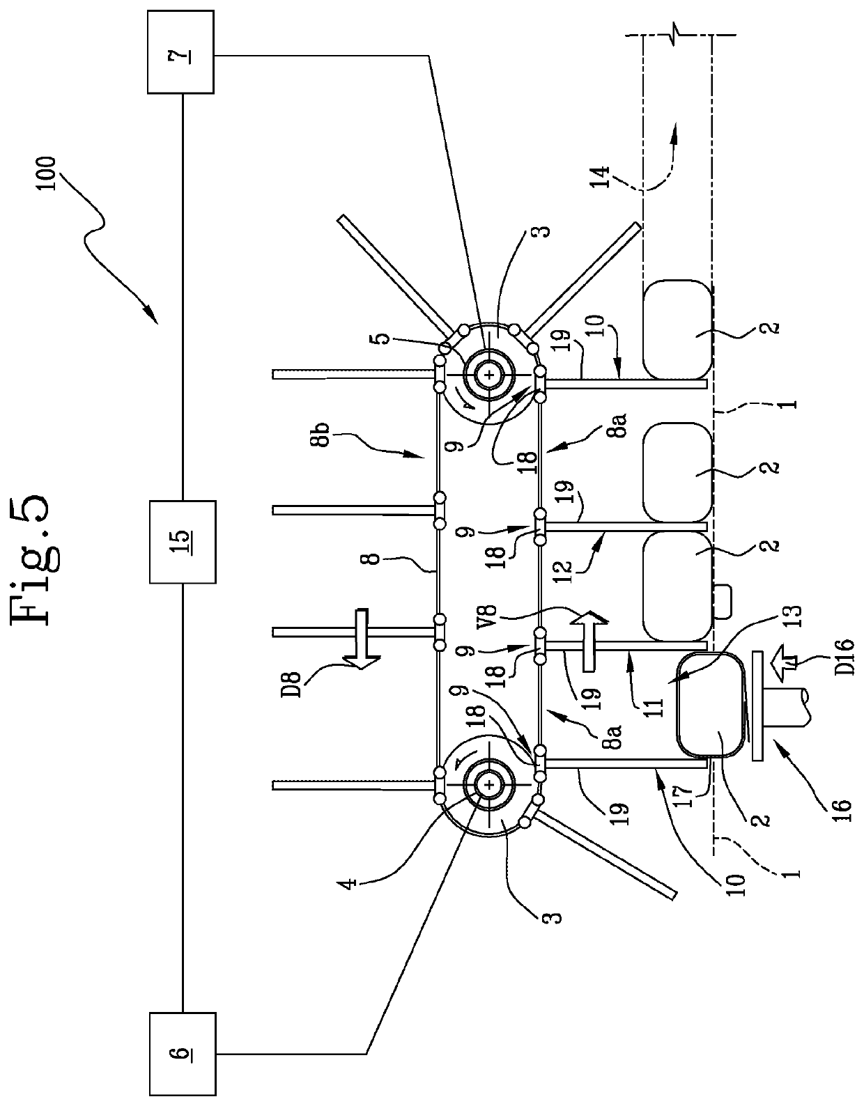
[0052]With reference to the accompanying drawings, in particular FIGS. 4 and 5, the machine according to the invention, labelled 100 in its entirety, is used for packaging soft products, such as, for example, but without restricting the scope of the invention, those for sanitary use, such as rolls of tissue paper products such as, for example, rolls of paper for sanitary and / or household use or unwoven products such as nappies.

[0053]Again with reference to FIGS. 4 and 5, the machine 100 comprises a plane 1 for feeding groups 2 of products (where groups of products may refer to a single product being wound, or a plurality of products arranged on several rows and several layers).

[0054]The feed plane 1 is usually delimited by a pair of flanks.

[0055]The machine 100 also comprises a plurality of pulleys 3 positioned at the two ends of the feed plane 1 and connected on at least two power-driven shafts 4, 5 (usually coaxial to each other and completed by a pair of driven shafts, but merely...


PUM

PropertyMeasurementUnit
distanceaaaaaaaaaa
sizeaaaaaaaaaa
timeaaaaaaaaaa

Abstract

A machine for packaging soft products, including a conveyor defining a ring-shaped path having an active linear lower branch facing a feed plane and a non-active linear upper branch. Each of a plurality of carriages supports a tooth, projecting towards the feed plane during the passage on the lower branch, and configured for retaining and feeding along the feed plane the groups of products. A transfer device moves one group of products at a time, with a corresponding sheet of wrapping material folded into a “U” shape around the group, towards the feed plane and to a receiving compartment defined by a first and a second tooth, along a second direction transversal to a first direction. Each tooth includes a head permanently connected to the carriage and an operating portion in contact with the groups which can be separated from and reconnected to the head.

Description

TECHNICAL FIELD[0001]This invention relates to a machine for packaging soft products, such as, for example, but without limiting the scope of the invention, those for sanitary use, in particular rolls of tissue paper products such as rolls of paper for sanitary and / or household use or unwoven products such as nappies.BACKGROUND ART[0002]Currently, in the automatic machines which perform the packaging of the above-mentioned products, the products are grouped together in one or more layers, such as, for example, layers composed of several rolls aligned in rows, and they are sent to a feed station downstream of which there is a packaging unit.[0003]For reasons of simplicity, a machine for making packaging rolls is described below.[0004]The purpose of the packaging unit is to wrap the group of rolls with a sheet of heat-sealable wrapping material, for example, but without restricting the scope of the invention, made of transparent polypropylene, and to stabilise the wrapper thus obtaine...

Claims


Application Information

Patent Timeline
Patent Type & Authority Applications(United States)
IPC IPC(8): B65B25/14B65B11/22B65B59/04B65B49/08
CPCB65B11/22B65B25/146B65B59/04B65B49/08B65B59/005
Inventor RASI, MICHELEROSSI, WILLIAM
Owner TISSUE MACHINERY
Learn More