Image forming apparatus and method of controlling transfer current in the image forming apparatus

a technology of image forming apparatus and transfer current, which is applied in the direction of electrographic process apparatus, instruments, optics, etc., can solve the problems of reducing productivity, reducing transfer properties, and long time for atvc, so as to prevent the change of transfer properties and reduce productivity

Active Publication Date: 2014-12-02
KONICA MINOLTA BUSINESS TECH INC
View PDF4 Cites 0 Cited by
  • Summary
  • Abstract
  • Description
  • Claims
  • Application Information

AI Technical Summary

Benefits of technology

[0011]An object of the present invention is to, in the case where the transfer member is under constant voltage control, prevent change in transfer properties due to the reduction in resistance of the transfer member without reducing the productivity.

Problems solved by technology

However, if continuous printing is performed by a print job for a lot of sheets, the resistance of the transfer member decreases to cause excess current, thus degrading the transfer properties (see FIGS. 13A and 13B).
However, the ATVC takes long time, thus causing reduction in productivity.
The techniques of the aforementioned Patent Literatures 1 and 2 cannot cope with the change in density caused by excess current due to changing resistance of the transfer member under constant voltage control.

Method used


Image

  • Image forming apparatus and method of controlling transfer current in the image forming apparatus
  • Image forming apparatus and method of controlling transfer current in the image forming apparatus
  • Image forming apparatus and method of controlling transfer current in the image forming apparatus

Examples


verification experiment

[Verification Experiment]

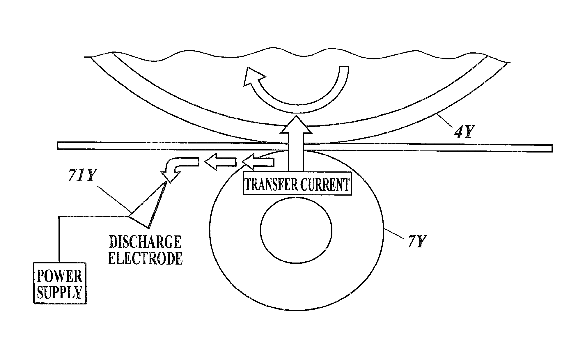
[0071]The verification experiments used an image forming apparatus having a configuration including a discharge electrode near the primary transfer roller of each color (see FIG. 9). Table 1 shows the specifications of the image forming apparatus. In the verification experiments, 1000 sheets were continuously printed with the aforementioned applied voltage control process, and the image density was measured for each certain number of prints. The measurement of the density used a reflection density meter (Spectolino by Gretag Macbeth). As the applied voltage control curves, the applied voltage control curves obtained by the pre-experiment (FIG. 10) were used.

[0072]

TABLE 1ApparatusFull color machine withintermediate transfer bodyProcess Speed300 mm / secIntermediateMaterialPolyimide semi-conductingTransfer BodybeltProfileThickness: 80 μmCircumferential length:861 mmWidth: 362 mmResistivity10 to 11 LogΩ / TransferOuter DiameterΦ22 (core: Φ10)RollerMaterialSingle la...


PUM


Abstract

An image forming apparatus includes: a transfer member, a controller, a discharge electrode, a detector, and a storage section. The controller, based on an amount of change between parameter value detected by the detector after transfer by the transfer member and parameter value stored in the storage section, determines voltage necessary for the discharge electrode to take the same amount of current as an increase in transfer current of the transfer member from previously determined transfer current and applies the determined voltage to the discharge electrode.

Description

BACKGROUND OF THE INVENTION[0001]1. Field of the Invention[0002]The present invention relates to an image forming apparatus and a method of controlling transfer current.[0003]2. Description of Related Art[0004]In a conventional electrophotographic image forming apparatus, a transfer material or an intermediate transfer body passes between a photoreceptor and a transfer member. During the passage, a toner image on the photoreceptor is transferred to the transfer material or intermediate transfer body by a transfer bias applied to the transfer member. The transfer bias is generally controlled under constant voltage control or constant current control.[0005]The transfer member is generally composed of a transfer roller. The transfer roller is made of a material having an electric resistance (hereinafter, referred to as a resistance) highly dependent on the environment. Various techniques to address environmental change have been proposed.[0006]For example, Patent Literature 1 (Japanese...

Claims


Application Information

Patent Timeline
Patent Type & Authority Patents(United States)
IPC IPC(8): G03G15/14G03G15/16
CPCG03G2215/0135G03G15/1675
Inventor HAYAMI, TOSHIKI
Owner KONICA MINOLTA BUSINESS TECH INC
Why Eureka
Try Eureka