
Portable cell phone battery charger using solar energy as the primary source of power

a solar energy and charger technology, applied in transportation and packaging, secondary cell servicing/maintenance, electrochemical generators, etc., can solve the problem that the battery may only last a few hours

Inactive Publication Date: 2005-12-20
HSU PO JUNG JOHN
View PDF29 Cites 131 Cited by
  • Summary
  • Abstract
  • Description
  • Claims
  • Application Information

AI Technical Summary

Benefits of technology

[0011]An important advantage of the present invention is that it provides a portable means for charging the battery of a cellular phone or other battery powered device without requiring connection to residential or commercial power source.
[0012]Another advantage of the present invention is that it provides a device of the type described that can be used to charge or power a phone with or without ambient sunlight.
[0013]Still another advantage of the present invention is that it provides a device of the type described that in the presence of sunlight can recharge its own internal batteries.
[0014]These and other object sand advantages of the present invention will no doubt become apparent to those skilled in the art after having read the following detailed description of the embodiment illustrated in the several figure of the drawing.

Problems solved by technology

However, depending on the frequency or duration of use of the cellular phone, leaving the phone in the “ON” mode or engaging in air time talking to another person, the battery may only last for a few hours.

Method used


Image

  • Portable cell phone battery charger using solar energy as the primary source of power
  • Portable cell phone battery charger using solar energy as the primary source of power
  • Portable cell phone battery charger using solar energy as the primary source of power

Examples


Embodiment Construction

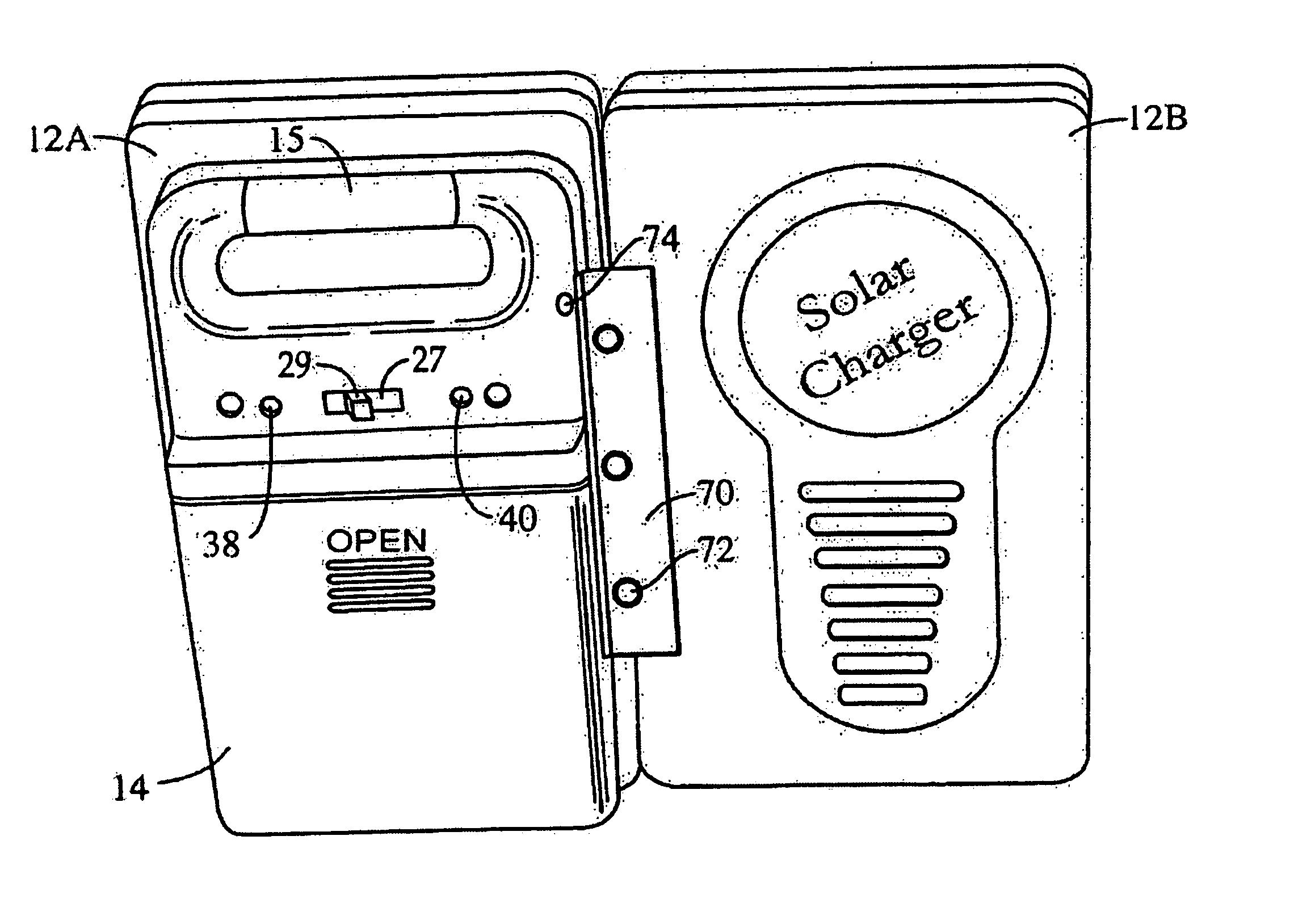
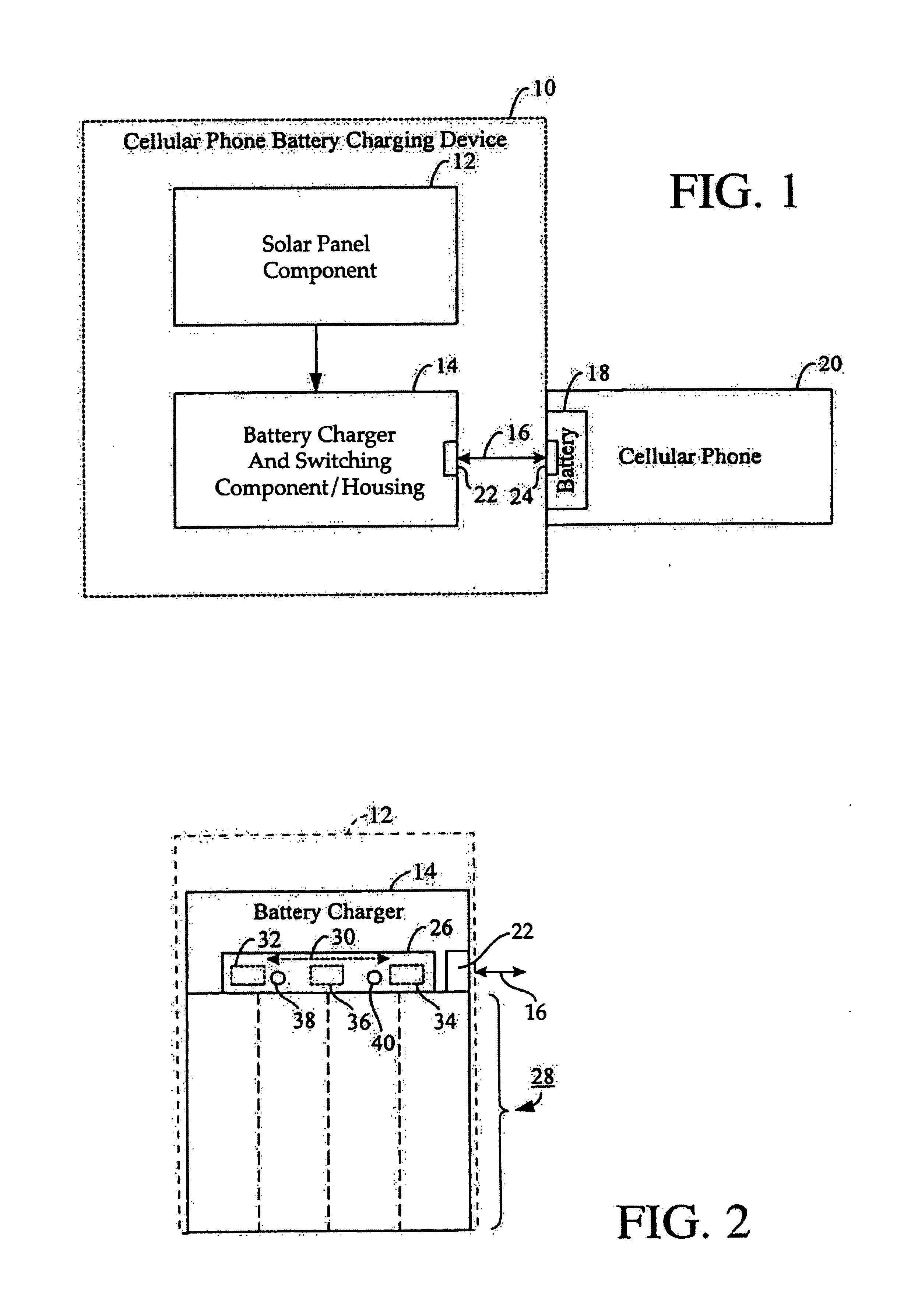
[0022]Referring now to the drawing, FIG. 1 is a block diagram schematically illustrating an exemplary cellular phone battery charging device in accordance with the present invention. The device 10 includes a solar energy collecting component 12 including two solar enemy collecting panels, a battery charger and switching component disposed in a separate housing 14, and an adapter cable 16 for providing power to and / or charging the battery 18 in a cellular phone 20 connected thereto.

[0023]The battery charger and switching component within housing 14 is suitably electrically connected as suggested by the line 13 to the solar panel component 12 for receiving electrical power converted from solar energy by the solar panels. The technology of converting solar energy to electrical power is well known to those skilled in the art.

[0024]The adapter cable 16 has on one end a first plug (not shown) for connection to a receptacle 22 in the battery charger and switching component housing 14, and ...


PUM


Abstract

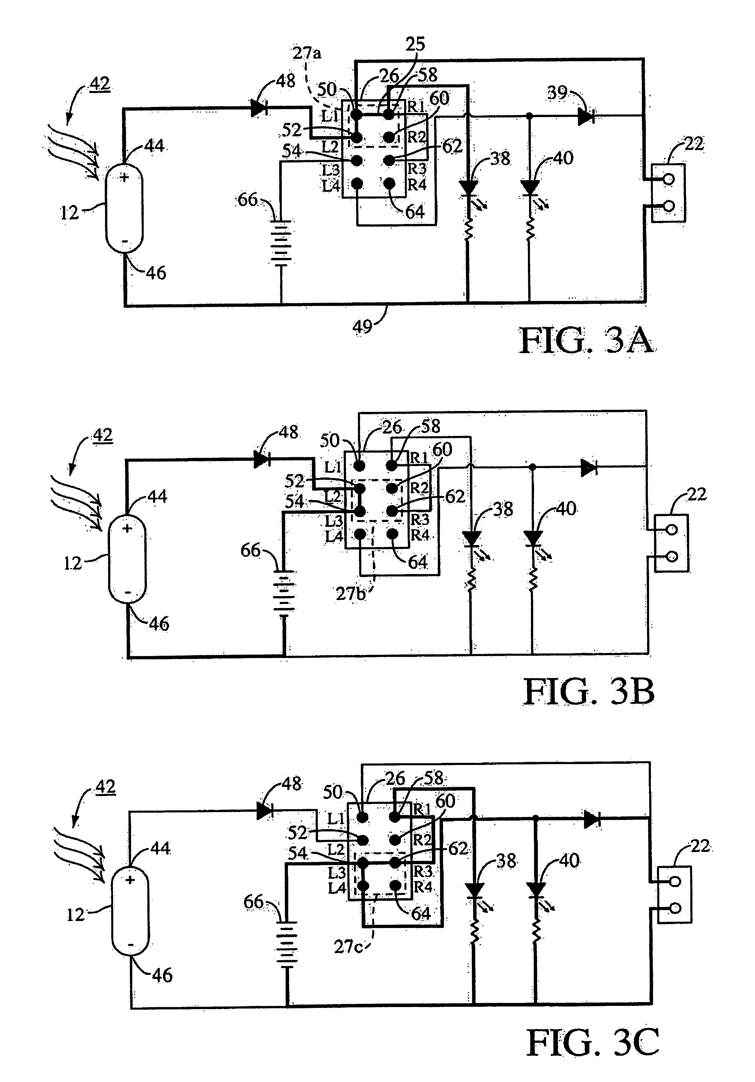
A portable, cellular phone battery charger using solar energy as the primary source of power and including two separate solar panels and a battery / switch containing unit. The two panels are hingedly connected together, and the battery / switch containing unit is hingedly connected to the back side of one of the panels. The assembly is pivotable between a retracted configuration in which the three component parts lie in parallel planes, and a deployed configuration in which the two solar panels lie in one plane and the battery / switch unit lies in another plane angularly intersecting the solar panel plane. The device is selectively operable in three different modes; namely, a first mode in which the solar panels are connected to charge or power a cell phone; a second node in which the solar panels are connected to charge the device's internal battery, and a third mode in which the internal battery is used to charge or power a phone coupled to the device.

Description

CROSS-REFERENCE TO RELATED APPLICATIONS[0001]This patent application claims the benefit of the filing date of U.S. Provisional Patent Application Ser. No. 60 / 347,232, filed Jan. 8, 2002 and entitled “CELLULAR TELEPHONE BATTERY CHARGER”, the entire contents of which is hereby expressly incorporated by reference.FIELD OF THE INVENTION[0002]The present invention relates generally to solar energy powered battery charging devices and more particular to a compact, portable cellular telephone battery charger using solar energy as the primary source of power.BACKGROUND OF THE INVENTION[0003]Most cellular phones are equipped with rechargeable batteries which can be recharged through a power conversion adapter used in conjunction with household alternating current (AC) power or through a power conversion adapter used in conjunction with a 12-volt cigarette lighter socket provided in an automobile. However, depending on the frequency or duration of use of the cellular phone, leaving the phone ...

Claims


Application Information

Patent Timeline
IPC IPC(8): H02J7/35
CPCH02J7/355H02J7/35
Inventor HSU, PO-JUNG JOHN
Owner HSU PO JUNG JOHN
Learn More