Right angle measuring device

a technology of measuring device and right angle, which is applied in the direction of measuring device, fixed angle setting out, instruments, etc., can solve the problems of poor use effect, high cost, and high cost, and achieve the effect of improving the accuracy of the measurement device, improving the accuracy, and improving the accuracy

Inactive Publication Date: 2005-12-27
DOUBLET DANIEL P
View PDF15 Cites 19 Cited by
  • Summary
  • Abstract
  • Description
  • Claims
  • Application Information

AI Technical Summary

Problems solved by technology

These right angle measuring devices do not resist shocks and are only precise for small dimensions (less than 2 meters).
Amateur gardeners cannot make good use of this instrument which is not suitable for surfaces such as lawns, gardens, and alleys.
This process has the advantage of excellent precision, but its use is old-fashioned, painstaking, complicated and requires the participation...

Method used


Image

  • Right angle measuring device
  • Right angle measuring device
  • Right angle measuring device

Examples


example use

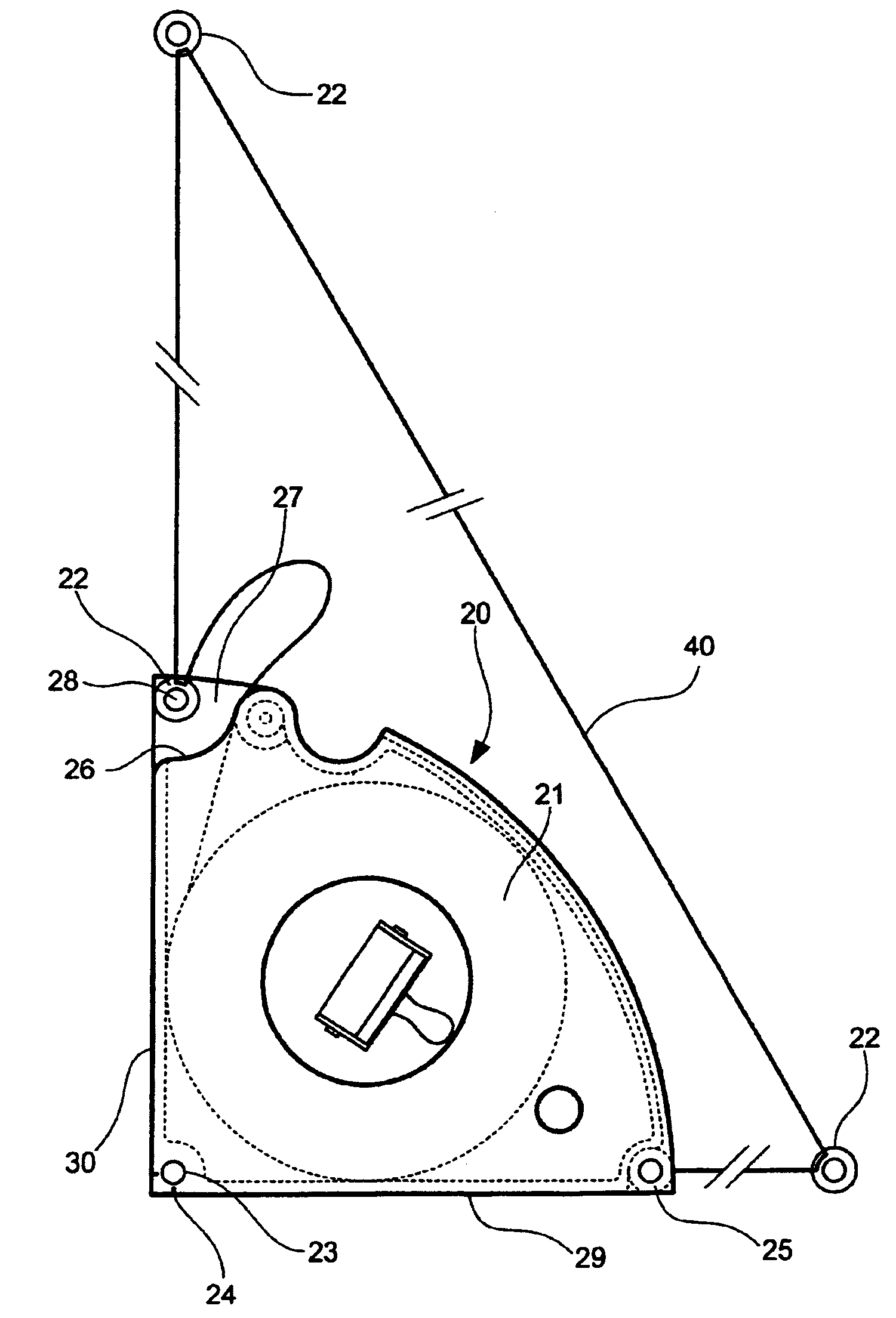
[0085]Draw the perpendicular to a straight line D at a point P using the housing 20 in the form of a right angle measuring device with three winders.[0086]Place the hole 23 of the housing 20 at P and use a headless nail or a peg to hold it in place.[0087]Take the winder 32 out of the housing 20 and hold it in place on the straight line D using a plug or a headless nail or a peg passing through the hole 34. At the same time as the winder 32 comes out of the housing 20, the yarn in the winder starts to unwind and continues until it reaches a stop.[0088]Take the winder 33 out of the housing 20 and hold it in position using a plug or a headless nail or a peg passing through the hole 34. At the same time as the winder 33 comes out of the housing 20, the yarn of the winders 32 and 33 unwinds until they reach the stop.

[0089]Note that the tensioned yarn between the mobile winder 33 and the housing 20 is perpendicular to the straight line D at P.

[0090]Note that the lengths of each of the thr...


PUM


Abstract

The invention concerns a device comprising a flexible and non-elastic yarn divided by at least three retaining means fixed to predetermined locations and at least three fixing means adapted to support the retaining means and whereof the diameter of each fixing means is substantially equal to the internal diameter of the retaining means so as to position the yard along a direction perpendicular to that of the axis of the corresponding fixing means.

Description

CROSS-REFERENCE TO RELATED APPLICATION[0001]This Application is a Section 371 National Stage Application of International Application No. PCT / FR02 / 01474 filed Apr. 27, 2002 and published as WO 02 / 088626 on Nov. 7, 2002, not in English.FIELD OF THE INVENTION[0002]Device designed to materialise limits perpendicular to existing or future limits, useable particularly in building, construction or do-it-yourself work.[0003]The purpose of this invention is a device designed to materialise limits perpendicular to existing or future limits, particularly for building or construction work, do-it-yourself work, etc.BACKGROUND OF THE INVENTION[0004]This device is designed firstly for use by do-it-yourself enthusiasts and amateur gardeners, for example, and also for professionals such as brick layers, tilers, electricians, carpenters, roofers, gardeners, landscape artists, etc.[0005]In the context of their activities, these persons are frequently confronted with the problem that consists of mater...

Claims


Application Information

Patent Timeline
IPC IPC(8): G01B3/10G01B5/245G01C15/12
CPCG01B5/245G01C15/12G01B3/1084
Inventor DOUBLET, DANIEL P.
Owner DOUBLET DANIEL P
Why Eureka
Try Eureka