Solid core concrete block and method of making a concrete block retaining wall

a concrete block and solid core technology, applied in the field of concrete block retaining walls, to achieve the effect of convenient stacking

Inactive Publication Date: 2005-12-27
CLARK RYAN +2
View PDF31 Cites 32 Cited by
  • Summary
  • Abstract
  • Description
  • Claims
  • Application Information

AI Technical Summary

Benefits of technology

[0006]In view of the foregoing, it is a primary objective of the subject invention to provide a plurality of solid core concrete blocks that can be easily stacked one on top of the other for forming different designs, sizes and shapes of retaining walls.

Problems solved by technology

None of the above mentioned prior art patents specifically disclose the unique features, structure and function of the subject solid core concrete block and method of making a concrete block retaining wall as described herein.

Method used


Image

  • Solid core concrete block and method of making a concrete block retaining wall
  • Solid core concrete block and method of making a concrete block retaining wall
  • Solid core concrete block and method of making a concrete block retaining wall

Examples


Embodiment Construction

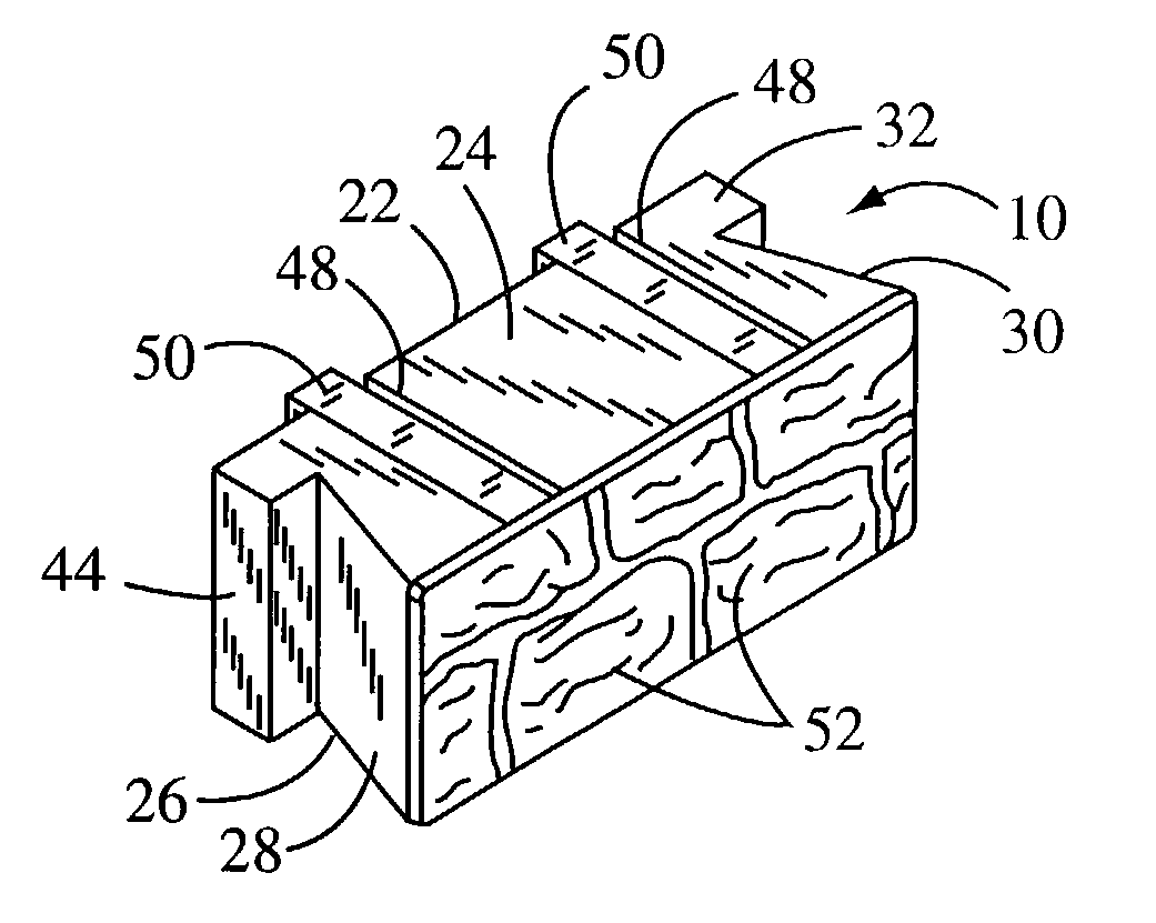
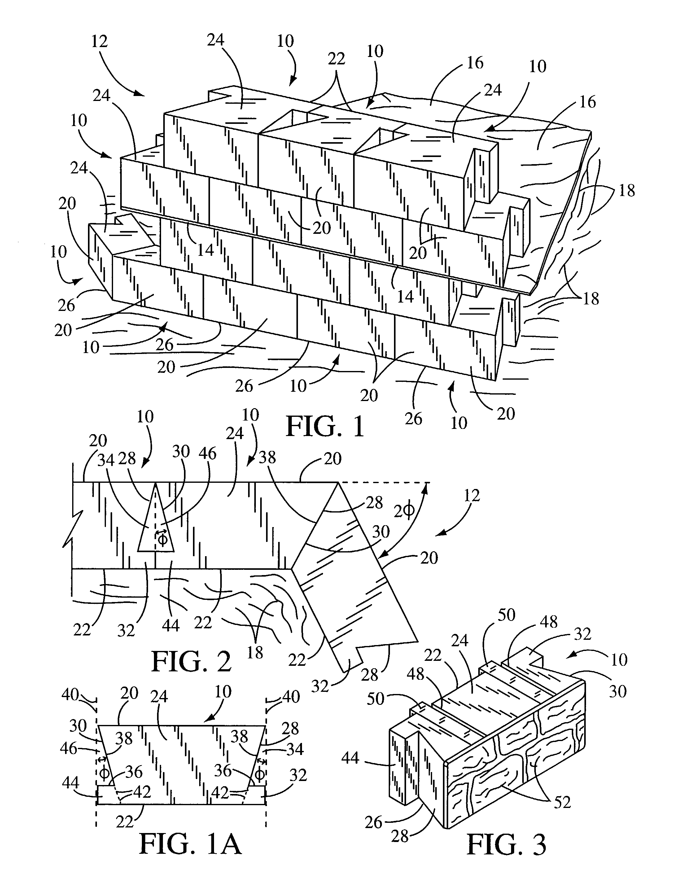
[0024]In FIG. 1, a perspective view of a plurality of the subject solid core concrete blocks are shown and having general reference numeral 10. The blocks 10 are used for forming a concrete block retaining wall. The retaining wall is shown having a general reference numeral 12. The retaining wall can be straight wall, curved wall or angled wall or a combination of both. This drawing illustrates four rows of the blocks 10 with one side 14 of a fabric sheet 16 received between the second and third rows of blocks 10. The fabric sheet 16 extends from the rear of the retaining wall 12 and is received over dirt backfill 18. As the rows of blocks 10 extend upwardly additional fabric sheets 16 can be installed between every row of block or as required with additional compacted dirt backfill 18 placed on top of the sheets. The sheets 16 are used to hold the retaining wall in place due to pressure from the compacted dirt behind the wall. It should be noted that the solid core blocks have suff...


PUM

PropertyMeasurementUnit
angleaaaaaaaaaa
angleaaaaaaaaaa
angleaaaaaaaaaa

Abstract

A plurality of solid core concrete blocks used in forming a retaining wall. The retaining wall can be used in building construction, road construction, landscaping, hillside erosion control, gardens, and like applications. Also, the retaining wall can be a straight wall, an angled wall or a curved wall depending on the application. Each of the blocks includes a vertical front face and rear face, a horizontal top and bottom and a vertical first side and second side. The first side includes a first ear and two sides of an angular first notch next to the first ear. One side of the first notch is parallel to a length of the front and rear faces and forms a side of the first ear. A second side of the first notch is disposed inwardly into the block and at an angle of 10 to 45 degrees from a horizontal line perpendicular to a length of the front and rear faces. When the first ear is broken off, a length of the second side of the first notch is extended for engaging a side of another block having a second ear broken off. In this manner, the retaining wall can be angled or curved during the wall construction.

Description

BACKGROUND OF THE INVENTION[0001](a) Field of the Invention[0002]This invention relates to a concrete block retaining wall and more particularly, but not by way of limitation, to a unique solid core concrete block and a plurality of the concrete blocks used in building a concrete block retaining wall. The retaining wall can be used in building construction, road construction, landscaping, hillside erosion control, gardens, and like applications[0003](b) Discussion of Prior Art[0004]Heretofore, there have been a variety of different types of concrete blocks, bricks, railroad ties and other types of materials used in retaining wall construction. In U.S. Pat. No. 5,788,423 to Perkins, U.S. Pat. No. 6,000,183 to Newman and U.S. Pat. No. 5,465,544 to Ghahary different types of decorative face plates or facing panels are illustrated for attaching to the front of concrete blocks used in retaining walls. In U.S. Pat. No. 5,568,999 to Egan et al. and U.S. Pat. No. 5,992,102 to Ozawa, two dif...

Claims


Application Information

Patent Timeline
Patent Type & Authority Patents(United States)
IPC IPC(8): B28B17/00E02D29/02E04B2/00E04B2/02E04C1/39E04C2/04
CPCE02D29/0266E04C1/395B28B17/0018E04B2002/026E04B2002/0263E04B2002/0271
Inventor CLARK, RYANHUG, LAWRENCE J.MARTINEZ, MICHAEL J.
Owner CLARK RYAN
Why Eureka
Try Eureka