Rake wheel

a technology of rake wheel and rim, which is applied in the field of rake wheel, can solve the problems of needing replacement of the wheel, the aperture in the rim securing each tine in position will gradually wear and become enlarged, and the patent did not address the problem of bearing aperture wear, so as to reduce the amount of crops that blow. , the effect of prolonging the functional life of the wheel

Active Publication Date: 2005-12-27
MILLER FREDDIE
View PDF10 Cites 13 Cited by
  • Summary
  • Abstract
  • Description
  • Claims
  • Application Information

AI Technical Summary

Benefits of technology

[0011]A further object of the present invention is to provide a rake wheel with a rim and tines that may be shifted, to extend the functional life of the wheel.
[0012]Another object is to provide an improved rake wheel with a windshield that reduces the amount of crops that blow through the wheel, as compared to prior art shields.
[0013]Yet a further object of the present invention is to provide an improved rake wheel with a windshield that permits removal and replacement of the tines without removing the shield.

Problems solved by technology

One of the chief problems with prior art rakes is in the need for replacement of a wheel upon the breaking of a tine on the rake wheel.
However, the '145 patent did not address the problem of wear on the bearing aperture for each of the tines.
Thus, after a period of use, the aperture in the rim securing each tine in position will gradually wear and become enlarged.
This, in turn, causes the tine to fail to function properly, once the tine becomes to loose in the aperture.
Another problem with prior art rake wheels is the fact that they are less efficient if there is a crosswind.
In addition, such shields typically cover the fastener bolts for the tines, thereby requiring removal of the shield before it is possible to replace or repair a tine.

Method used


Image

  • Rake wheel
  • Rake wheel

Examples


Embodiment Construction

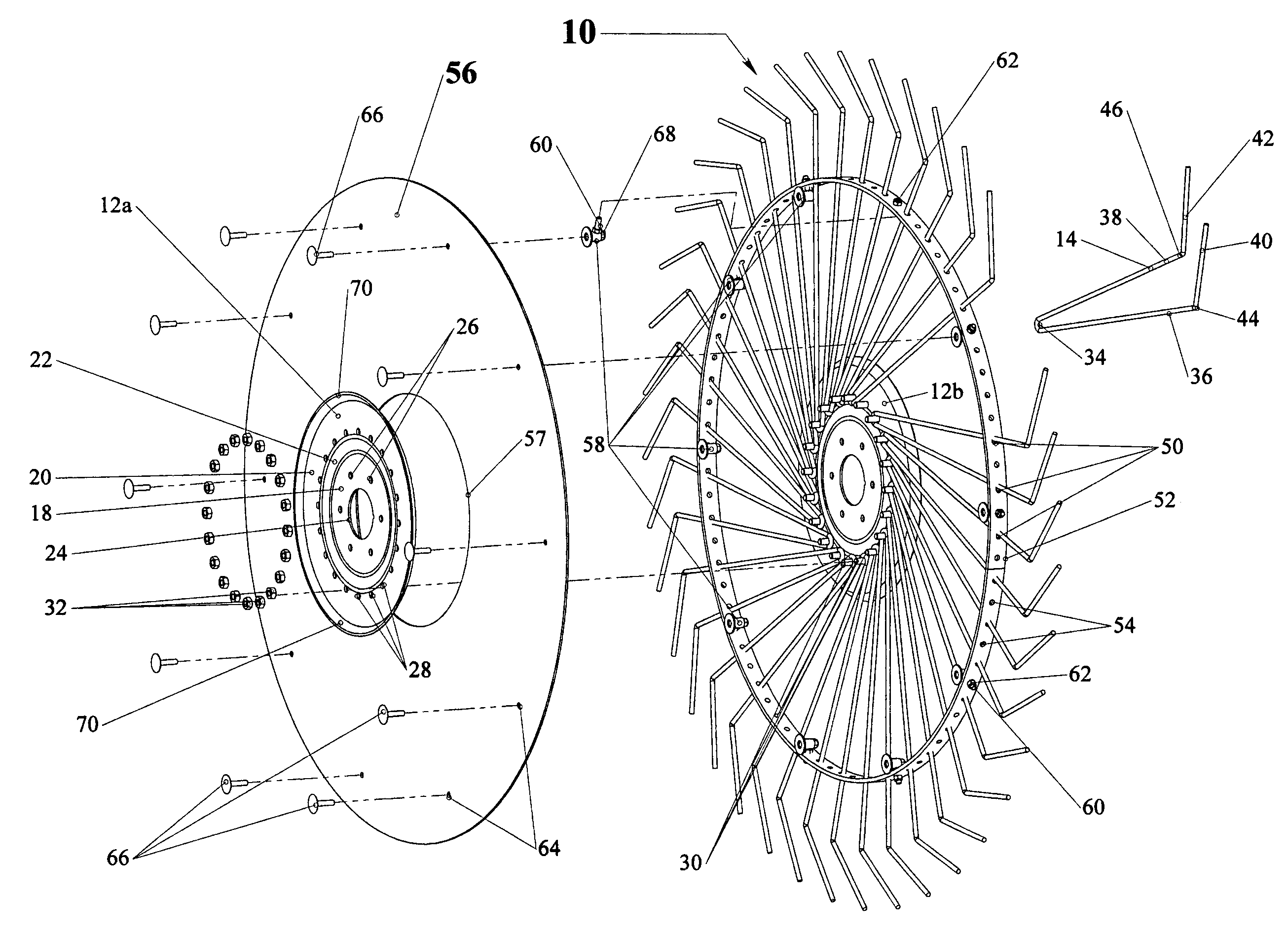
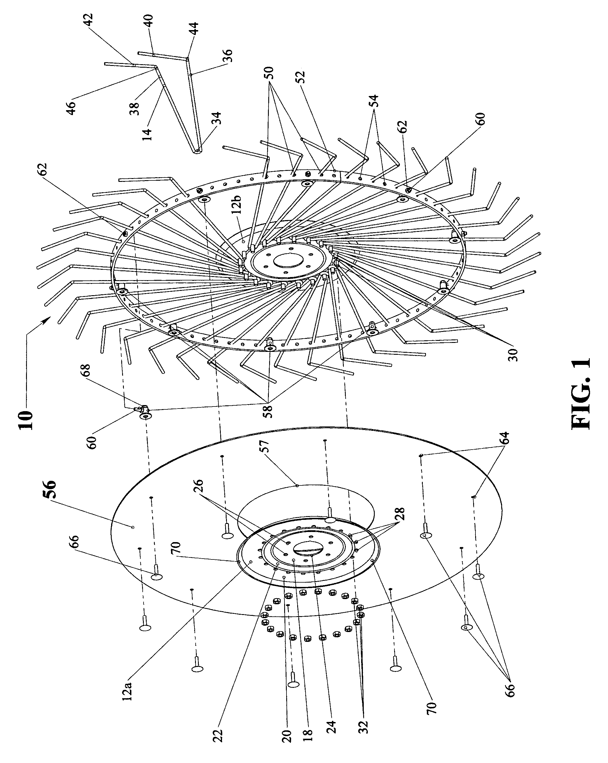
[0017]Referring now to the drawing, the rake wheel of the present invention is designated generally at 10 and includes a pair of identical and opposing flanges 12a and 12b from which a plurality of tines 14 extend. Tines 14 extend through a ring-shaped rim 16 for securement in the desired position for raking materials on the ground.

[0018]Because flanges 12a and 12b are identical, only flange 12a will be described in detail herein. Flange 12a is a disk-shaped member having a flat inner ring 18 and a flat outer ring 20. Outer ring 20 is parallel to and spaced radially and orthogonally outwardly from inner ring 18, and is connected to the inner ring by a sloped annular portion 22. Inner ring 18 has a central opening 24, which receives a shaft on an implement (not shown) so that the wheel 10 may be rotatably mounted on the implement in a conventional fashion.

[0019]Inner ring 18 extends radially outwardly from central opening 24, and has a plurality of apertures 26 formed therein, spaced...


PUM


Abstract

A rake wheel includes a hub and a plurality of tines connected to the hub and extending outwardly therefrom to an annular rim concentric with the hub. Each tine is journaled through a first plurality of apertures formed in the rim and projects outwardly from the rim. A second plurality of apertures is formed in the rim, having a size and shape substantially the same as the first plurality of apertures, and will receive the tines when the first set of apertures becomes worn or otherwise ineffective.

Description

CROSS-REFERENCES TO RELATED APPLICATIONS[0001](Not applicable)STATEMENT AS TO RIGHTS TO INVENTIONS MADE UNDER FEDERALLY SPONSORED RESEARCH AND DEVELOPMENT[0002](Not applicable)BACKGROUND OF THE INVENTION[0003](1.) Field of the Invention[0004]The present invention relates generally to farm implements for raking hay, cornstalks and other crops, and more particularly to an improved rake wheel that may be re-used rather than replaced after conventional wear and tear has occurred.[0005](2.) Background Information[0006]Rakes used in the agricultural field have been known for many years. Their most common use is in the raking of hay or alfalfa into a row so that a baler will work more efficiently in the preparation of bales. Rakes are also commonly used for the turning of a row of hay or the like so that the crop will dry uniformly and thoroughly.[0007]While rakes were initially used for crops such as hay, they have been put to more rigorous use by some farmers in cornfields and the like, ...

Claims


Application Information

Patent Timeline
Patent Type & Authority Patents(United States)
IPC IPC(8): A01D80/02
CPCA01D80/02
Inventor MILLER, FREDDIE
Owner MILLER FREDDIE
Why Eureka
Try Eureka