Wastewater treatment system and related method

a wastewater treatment system and wastewater technology, applied in biological water/sewage treatment, filtration separation, separation processes, etc., can solve the problems of reducing the efficiency of treatment, increasing maintenance requirements, and limiting the use of septic tanks to septic tanks, so as to minimize the efficiency of bacterial action and limit or eliminate the chance of bacteria clogging

Active Publication Date: 2014-09-18
SILVA ROBERT F +1
View PDF10 Cites 2 Cited by
  • Summary
  • Abstract
  • Description
  • Claims
  • Application Information

AI Technical Summary

Benefits of technology

[0008]It is an object of the present invention to provide a system for treating wastewater, or other waste fluids, in an aerobic process. It is also an object of the present invention to provide a treatment system that limits or eliminates the chance of bacteria clogging without minimizing the efficiency of the bacterial action on the solids content of the waste fluid. Further, it is an object of the present invention to provide an airlift pump function in a septic tank or other waste fluid container that aerates the fluid effectively regardless of the size of the container. Yet further, it is an object of the present invention to provide an airlift pump based treatment system wherein the pump may be selectably positioned within the container.
[0009]These and other objects are achieved with a waste treatment system comprising a septic tank with an included airlift tube and active air input into the tube. The air is supplied by a pump that is external to the tank and sized in accordance with the size of the tank. The air is forced by the pump into a conduit associated with the tube and terminating in a diffuser or other form of porous structure. The system is arranged to promote the generation of suspended growth bacteria and with ports that are substantially larger than the pores of existing systems. The bacteria are provided by an air supply that is diffused in the tube wherein the air carries naturally occurring bacterial spores. These design features substantially eliminate the limitations associated with fixed film bacteria growth promotion and any other features that may result in clogging that can impact treatment effectiveness and increase maintenance requirements. Specifically, the airlift tube includes one or more inlet ports and one or more outlet ports that are large enough to ensure that any solids will pass through and not block those ports.
[0011]The system of the present invention extends the functional life of a septic system by reducing clogging conditions without compromising aerobic bacteria action. It is also effective at reducing the waste strength of effluent exiting the tank by, among other things, reducing fats, oils and grease in the effluent. That is accomplished by the turbulent action of the fluid caused by the air diffusion and the effective dispersion of the suspended growth bacteria. While the system of the present invention is suitable for residential and commercial septic systems, it is also suitable for use in other fluid containment systems to be treated including, but not limited to a mechanism to convert agricultural waste into fertilizer.

Problems solved by technology

However, the growth media can become clogged over time whether by bacteria growth or other solids in the fluid, such as hair, for example, thereby reducing treatment efficiency and increasing maintenance requirements.
As a result, they are limited in their usage to septic tanks having a capacity of no more than 1500 gallons.
That haphazard fix in the turbulent environment of the tank can cause the tube to fall over and become substantially ineffective.
Another limitation of existing systems is that they require the use of ballasting to keep them in a fixed position within the tank.
Unfortunately, there is a tendency for the fluid and contents entering the tank to be acidic.
If that acidity is too much, the bacteria can be harmed and thereby rendered ineffective.

Method used


Image

  • Wastewater treatment system and related method
  • Wastewater treatment system and related method
  • Wastewater treatment system and related method

Examples


Embodiment Construction

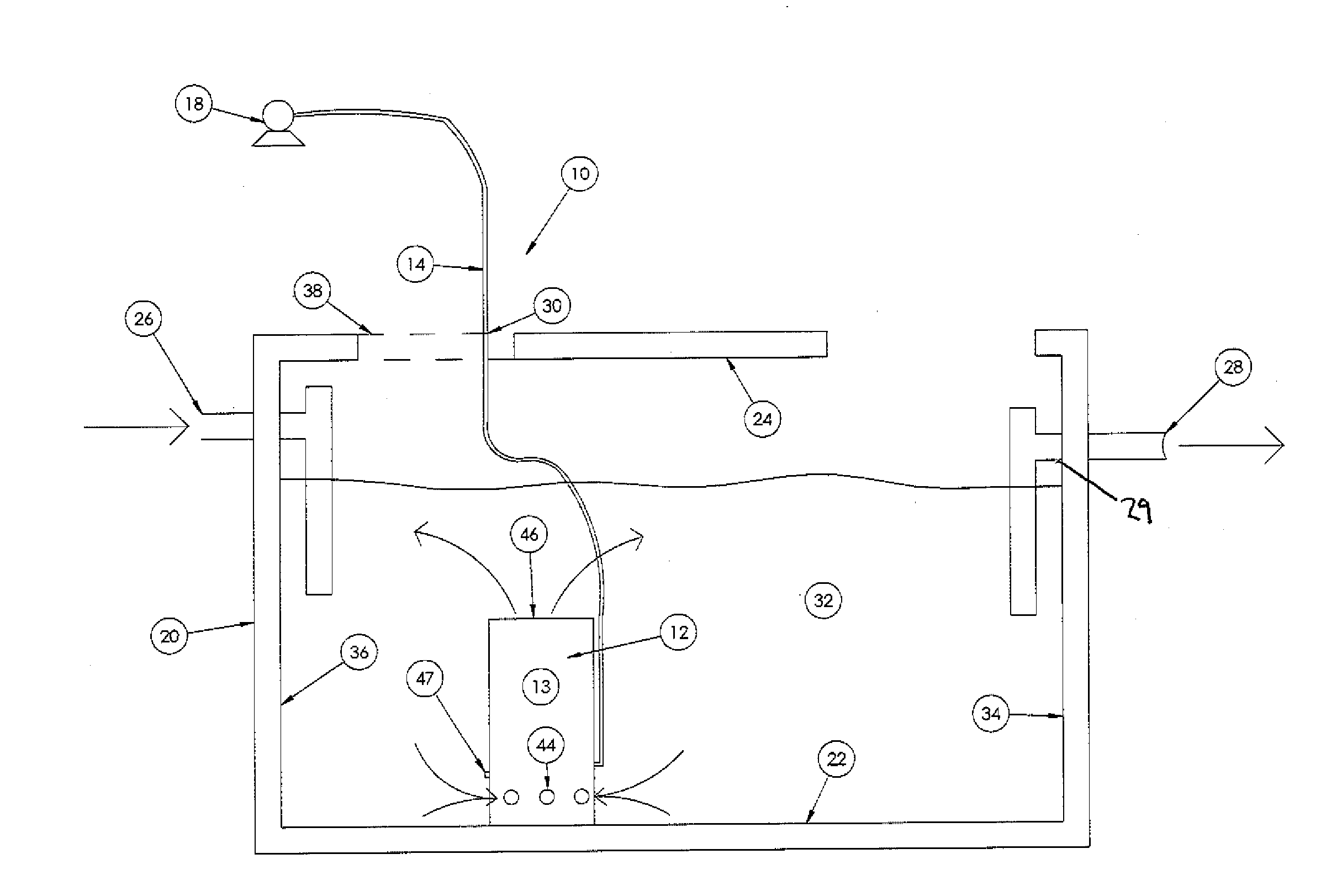
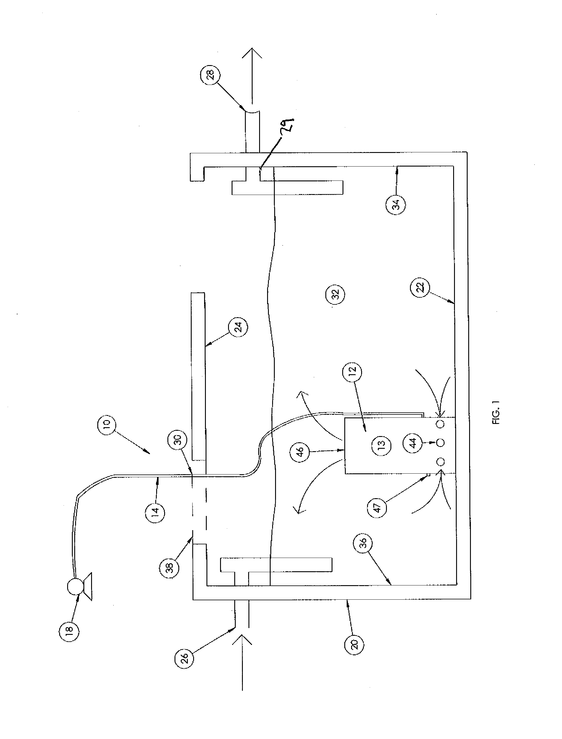
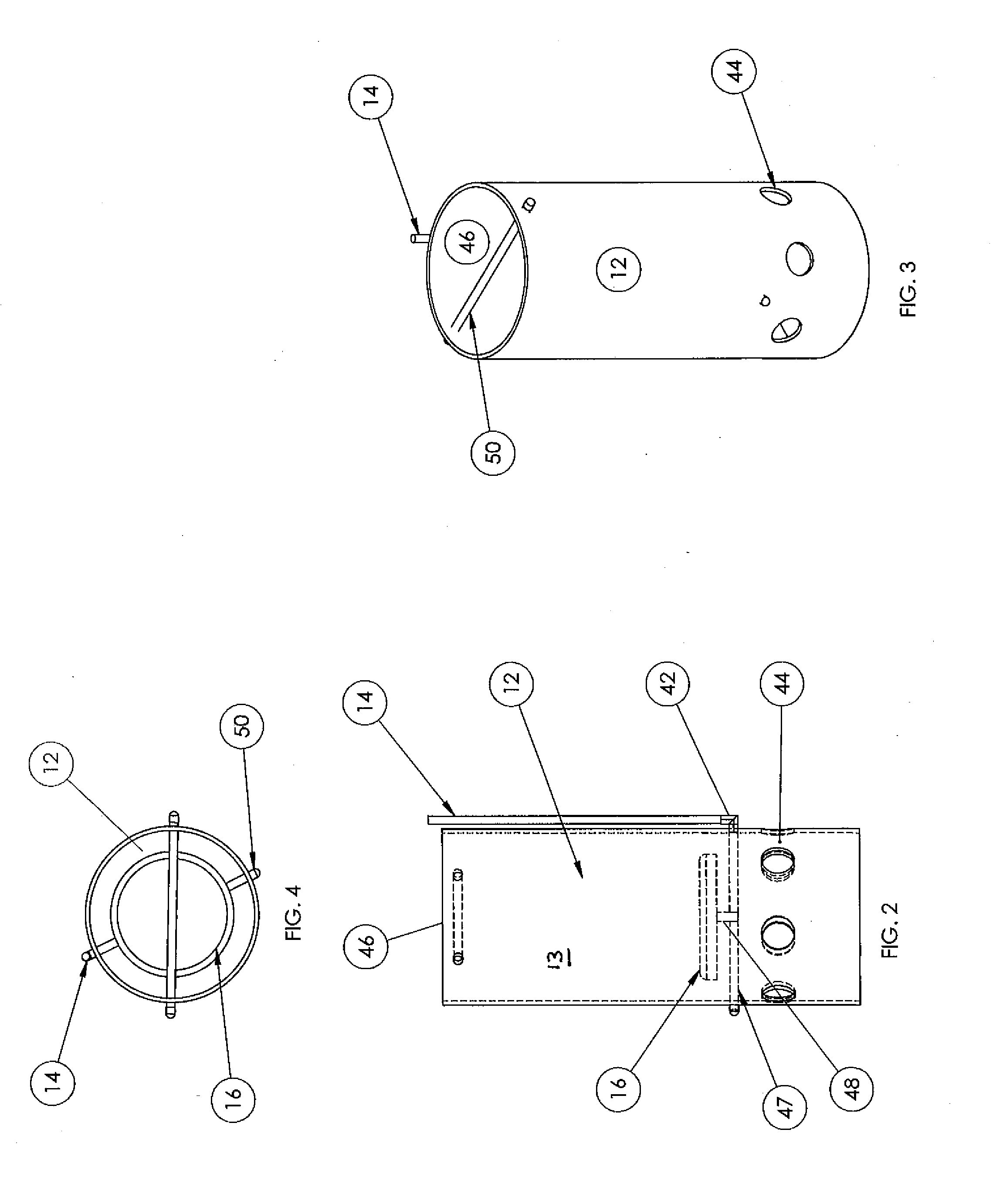
[0020]A first embodiment of a treatment system 10 of the present invention is shown in FIGS. 1-4. The system 10 includes an airlift tube 12, an aeration conduit 14 extending on or in the tube 12, a diffuser 16 within the tube 12 and connected to the conduit 14, and a pump 18 connectable to the conduit 14. The pump 18 is selected to be suitable to pump about 40 liters of air per minute into the tube 14. A suitable pump for that purpose is the Model No. ET40 diaphragm pump available from Charles Austen Pumps Ltd. of Surrey, England. As shown in FIG. 5, the system 10 may optionally include a regulating valve 19 to regulate air flow into the conduit 14.

[0021]The system 10 can be used in any container with a fluid to be treated to modify or remove solids in the fluid so that the fluid may be transferred to a location for storage, dissipation or another function. The system 10 is described herein with respect to the use in treating a fluid in a commercial or residential septic tank but it...


PUM

PropertyMeasurementUnit
diameteraaaaaaaaaa
heightaaaaaaaaaa
densityaaaaaaaaaa

Abstract

A system for treating a fluid in a container. The system includes an included airlift tube and active air input into the tube. The air is supplied by a pump that is external to the tank and sized in accordance with the size of the tank. The system is arranged to promote the generation of suspended growth bacteria. The bacteria are provided by an air supply that is diffused in the tube wherein the air carries naturally occurring bacterial spores. The airlift tube includes one or more inlet ports located below an air diffuser. The tube may be located on the floor of the tank, suspended from the ceiling of the tank or arranged to float within the tank. A plurality of tubes may be used together to treat fluids in containers larger than standard septic tanks. A pH neutralizing device may form part of the system.

Description

BACKGROUND OF INVENTION[0001]1. Field of the Invention[0002]The present invention relates to wastewater treatment. More particularly, the present invention relates to systems for treating wastewater including in septic tanks. Still more particularly, the present invention relates to wastewater treatment systems including airlift tubes.[0003]2. Description of the Prior Art[0004]Septic tanks and other sorts of wastewater treatment units are used to reduced the solids content of liquids prior to delivery to a fluid absorption field such as a leach bed. Some septic tanks are fairly stagnant in that incoming streams of solid and liquid waste are allowed to dwell in the tank until solids are separated from the liquid. The septic tank is configured so that the remaining effluent is allowed to flow to the absorption field, either directly or through a filter. Septic tanks with filtered outlets should be particularly effective at solids breakdown or removal to avoid filter clogging. Other ty...

Claims


Application Information

Patent Timeline
Patent Type & Authority Applications(United States)
IPC IPC(8): C02F3/22C02F1/66
CPCC02F1/66C02F3/223C02F3/20C02F3/22C02F2203/006C02F2203/008Y02W10/10
Inventor SILVA, ROBERT F.O'CONNOR, STEPHEN A.
Owner SILVA ROBERT F
Why Eureka
Try Eureka