Electric fish barrier for water intakes at varying depths

a technology of water intake and electric fish, applied in pisciculture and aquaria, hydraulic engineering apparatus, construction, etc., can solve the problems of frequent replacement, premature eroded copper cables, large fish reacting so violently in their attempt to change direction, etc., to achieve the effect of controlling the motion of fish

Active Publication Date: 2005-12-27
SMITH ROOT
View PDF11 Cites 39 Cited by
  • Summary
  • Abstract
  • Description
  • Claims
  • Application Information

AI Technical Summary

Benefits of technology

[0023]The present invention relates generally to an apparatus for shaping an electric field in water in order to effectively control the motion of fish at a variety of depths and spatial areas. The invention also relates to an electric fish barri...

Problems solved by technology

Because migration across such natural divides can upset the ecological balance, government mandates often require that construction and use of such waterways incorporate a method or apparatus for controlling ecologically harmful migration through these waterways.
Conversely, early experiments have demonstrated that if a moderately annoying region of the electric barrier is too narrow to allow a fish to turn around, and a rapidly swimming fish passes quickly through an “annoying” region and into a painful region, large fish have been observed to react so violently in their attempt to change direction that they have actually snapped their own spine.
Whether a fish barrier is effective, ineffective or harmful is thus a function of the shape of the boundary, the thickness and the intensity of a voltage gradient produced by an electric fish barrier.
Although copper conducts electricity well, galvanic effects between copper and water can prematurely erode copper cables, requiring frequent replacement.
Additionally, in water having a sulfur content, the ionized copper can form copper sulfate compounds in water, which can be poiso...

Method used


Image

  • Electric fish barrier for water intakes at varying depths
  • Electric fish barrier for water intakes at varying depths
  • Electric fish barrier for water intakes at varying depths

Examples


Embodiment Construction

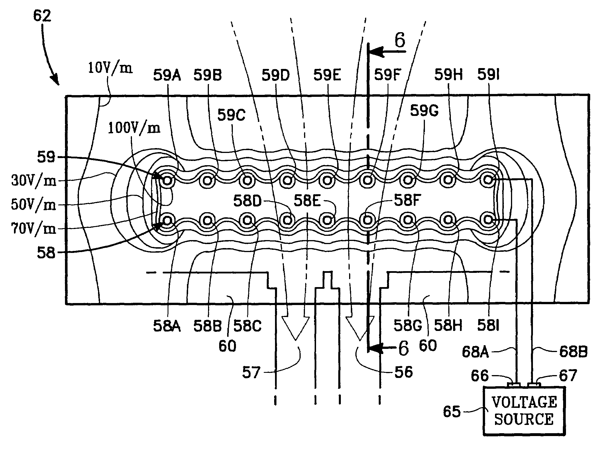
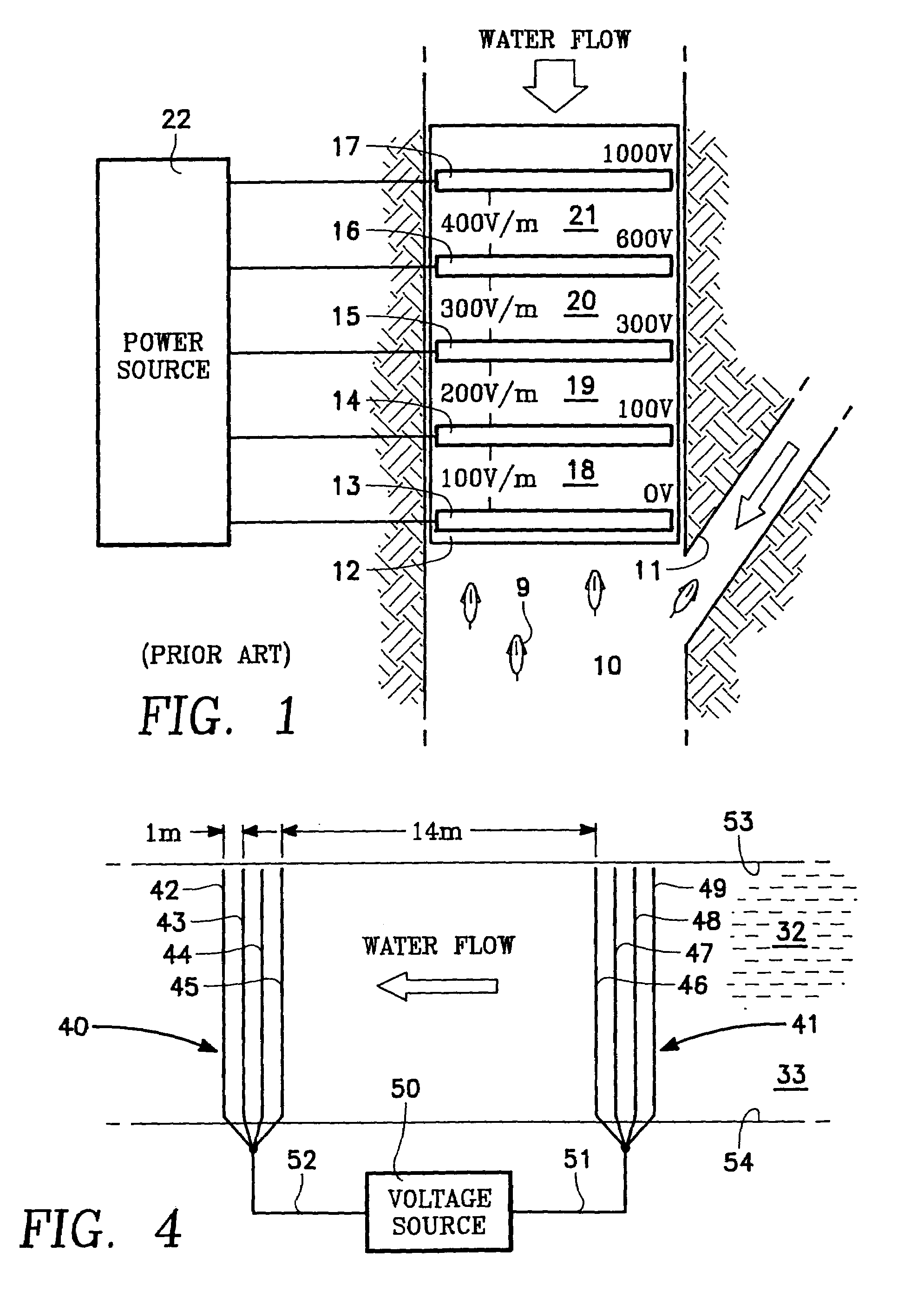
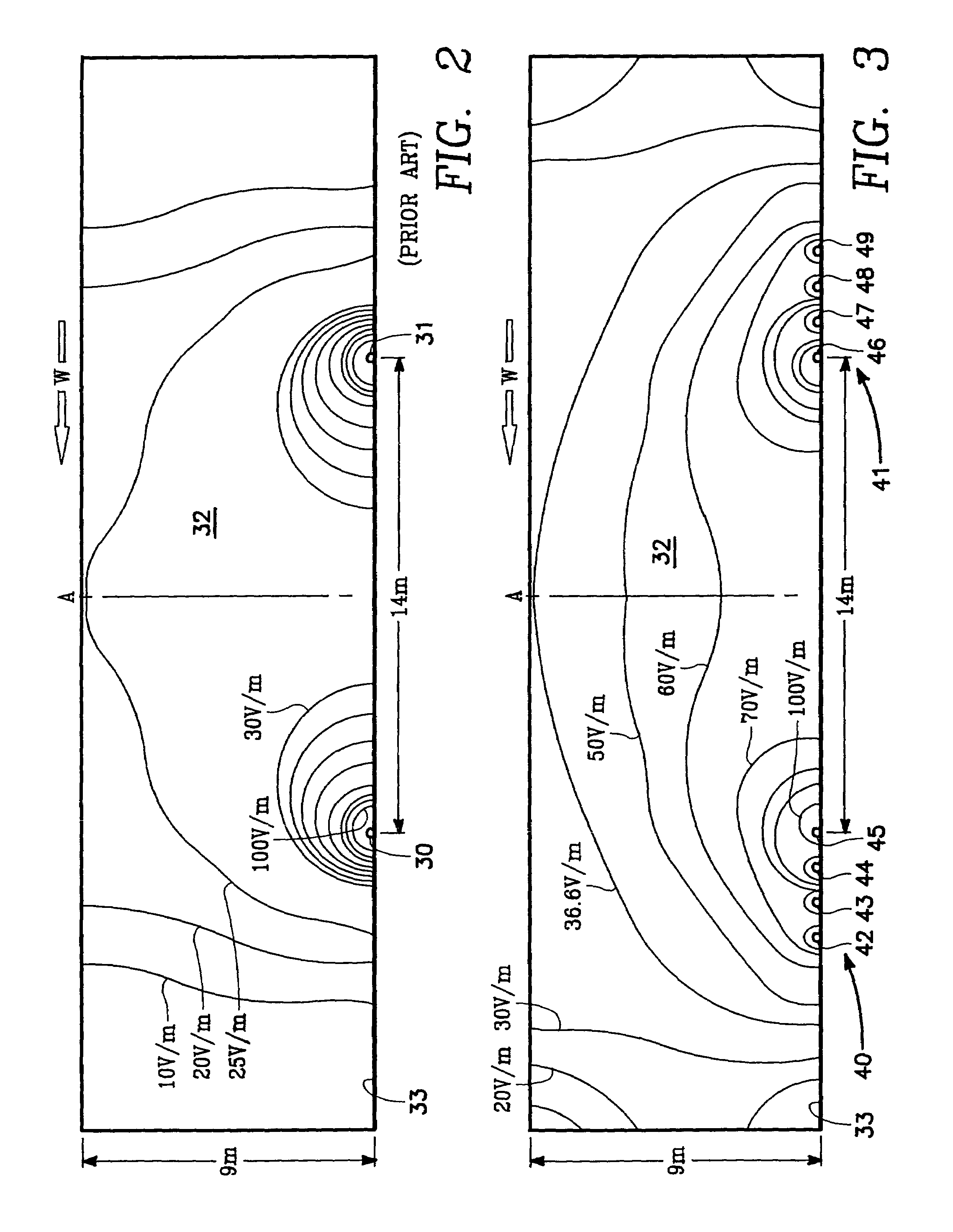
[0046]FIGS. 3 and 4 illustrate an embodiment of the invention for use in conjunction with a body of water such as a river, stream, or reservoir. As used herein, the term “river” is used generically, and can refer to any moving body of water, including, but not limited to, a river, stream, or a moving area of water within a reservoir leading to a water intake. Although applications herein are directed to moving water having an attraction flow, those skilled in the art will recognize that the principles described herein can be readily applied for use in conjunction with a stationary body of water. A first array 40 of multiple electrodes 42, 43, 44, 45 are electrically connected at a first common voltage and are spatially distributed over a select area in order to expand a range of a voltage field. A second array 41 of multiple electrodes 46, 47, 48 and 49 are electrically connected at a second common voltage and are also spatially distributed over a select area in order to expand a ra...


PUM


Abstract

An electric fish barrier for deterring fish from entering a water intake in a reservoir or along a waterway has a set of conductive members at a first voltage potential and a second set of conductive members at a second voltage potential. The conductive members are disposed on support piles extending up from the bottom of the reservoir. Each conductive member extends vertically between a pre-determined range of depths from an upper depth to a lower depth, forming a contiguous voltage gradient between the two sets of conductive members. Fish are drawn to the attraction flow of water flowing into the intake. The two sets of conductive members are oriented such that the attraction flow passes through the contiguous voltage gradient, thereby deterring the fish from following the attraction flow into the water intake.

Description

RELATED APPLICATIONS[0001]This application incorporates by reference U.S. patent application Ser. No. 10 / 677,400 to Smith et al., entitled ELECTRIC FISH BARRIER WITH SHAPED VOLTAGE GRADIENT, and filed concurrently with the present application.BACKGROUND OF THE INVENTION[0002]1. Field of the Invention[0003]The present invention relates to electric fish barriers used to govern the motion of fish in water. More particularly, the present invention relates to an electric fish barrier for discouraging fish from entering water intakes disposed at varying depths within a body of water.[0004]2. Description of Related Art[0005]The protection and preservation of natural resources includes the management of fish and game. Fish move about lakes, rivers, streams and reservoirs for a variety of reasons, including migration, spawning, and searching for food. Water intakes divert water for drinking, irrigation, and industrial uses. The introduction of fish into intakes is generally regarded as an un...

Claims


Application Information

Patent Timeline
IPC IPC(8): A01K61/00A01K79/02E02B1/00
CPCA01K79/02E02B1/006
Inventor SMITH, DAVID V.CARSTENSEN, LEE ROY
Owner SMITH ROOT
Why Eureka
Try Eureka