Unlock instant, AI-driven research and patent intelligence for your innovation.

Body frame structure for bicycle

Inactive Publication Date: 2005-12-27
HONDA MOTOR CO LTD
View PDF17 Cites 4 Cited by
  • Summary
  • Abstract
  • Description
  • Claims
  • Application Information

AI Technical Summary

Benefits of technology

[0014]The present inventor has determined that if a load transmitted from the rear frame 10 described above to the main frame member 5 can be transmitted as a load in an axial direction of the main frame member 5, then the main frame member 5 can support higher loads from the rear frame 10. Accordingly, a reduction in weight ca be achieved and the performance is improved.
[0015]An object of the present invention is to provide a body frame structure for a bicycle that raises steering performance of the vehicle and supports high loading transmitted to a body frame from a front wheel side and a rear wheel side.
[0018]According to a first characteristic of the present invention, the body frame is formed in the proximity of the head pipe with a box frame portion having a box-like shape such that it has a high rigidity. The box frame portion is divided at the twin tube portion thereof, to the left and right portions of a reduced thickness so as to have a low rigidity, a high load transmitted from the road surface to the head pipe through the front wheel and the front fork can be supported by the box frame portion. Further, a twist can be generated readily at a central portion of the body thereby to augment the steering performance of the vehicle.
[0019]According to a second characteristic of the present invention, the swing arm is mounted on the rear frame portion having an increased width in the bicycle widthwise direction, a twisting moment transmitted from the swing arm to the rear frame portion can be received by the two fulcra spaced from each other by a great distance. Consequently, the load to be generated by the twisting moment can be reduced. Where the load acting upon the rear frame portion is reduced in this manner, an increase of the rigidity of the swing arm mounting portion of the rear frame portion can be reduced and an increase of the weight of the rear frame portion can be decreased. Further, since the structure is offsets twisting of the swing arm, good rocking motion of the swing arm, e.g., expansion and compression of the cushion, is obtained.
[0020]According to a third characteristic of the present invention, the box frame portion, twin tube portion, rear cushion unit, and rear extension are disposed along a substantially straight line. Therefore, it is possible for the load transmitted from the swing arm to the box frame portion and the twin tube portion through the rear cushion unit to act substantially as an axial compression load on the box frame portion and the twin tube portion. For example, when compared with an alternative case wherein the load transmitted from the swing arm to the body frame acts as a bending load, a higher load can be supported by the body frame.
[0021]According to a fourth characteristic of the present invention, the rear cushion unit is disposed below the saddle frame, and the saddle frame and the rear frame portion surround the rear cushion unit. Consequently, the rear cushion unit can be protected from splattering debris and so forth.

Problems solved by technology

As the rigidity of a body frame increases, the distortion or twist of the body frame decreases.
However, if the rigidity of the body frame is excessively high, e.g., when the body frame is acted upon by an impact load from the load surface, the body frame reacts quickly to the impact load.
Therefore, the driver is liable to get tired because the driver is forced to react with the movement of the body.
In contrast, if the rigidity of the body frame is excessively low, then an excessively great twist of the body may occur or precise road surface information is not likely to be conveyed to the driver.
Accordingly, since the body frame reacts poorly to the movement of the driver, it is difficult to undertake quick motion.
With respect to the triangular frame of the document (1) described hereinabove, it is difficult to satisfy both the supporting of a high load and the augmentation of the steering performance.
However, if the rigidity of the main frame member 5 is increased, then the weight of the body is increased and the performance of the bicycle is deteriorated.

Method used


Image

  • Body frame structure for bicycle
  • Body frame structure for bicycle
  • Body frame structure for bicycle

Examples


Embodiment Construction

[0032]The present invention will hereinafter be described with reference to the accompanying drawings. It is to be noted that the drawings should be viewed in the direction corresponding to a proper reading of the reference characters.

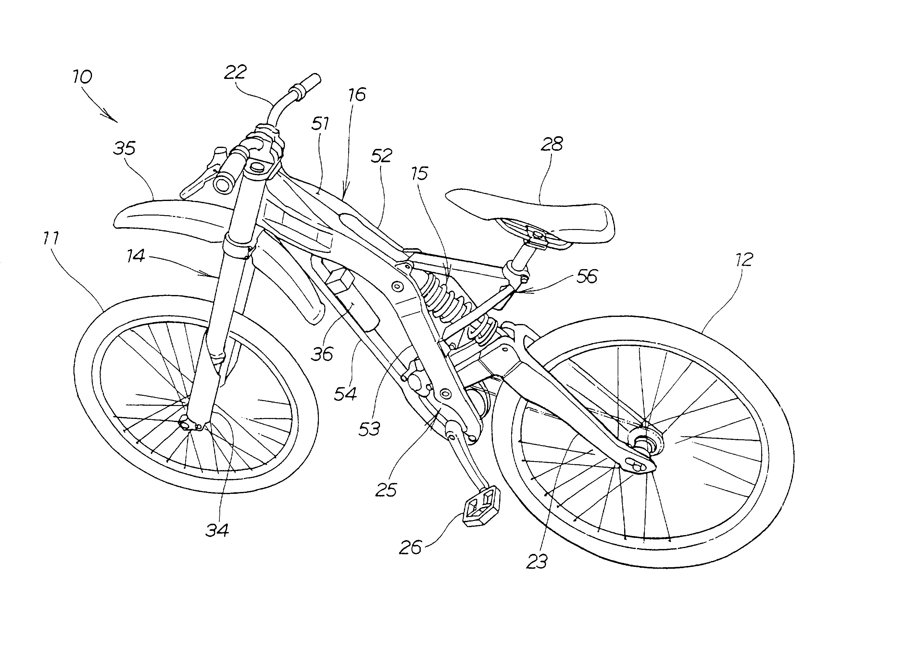
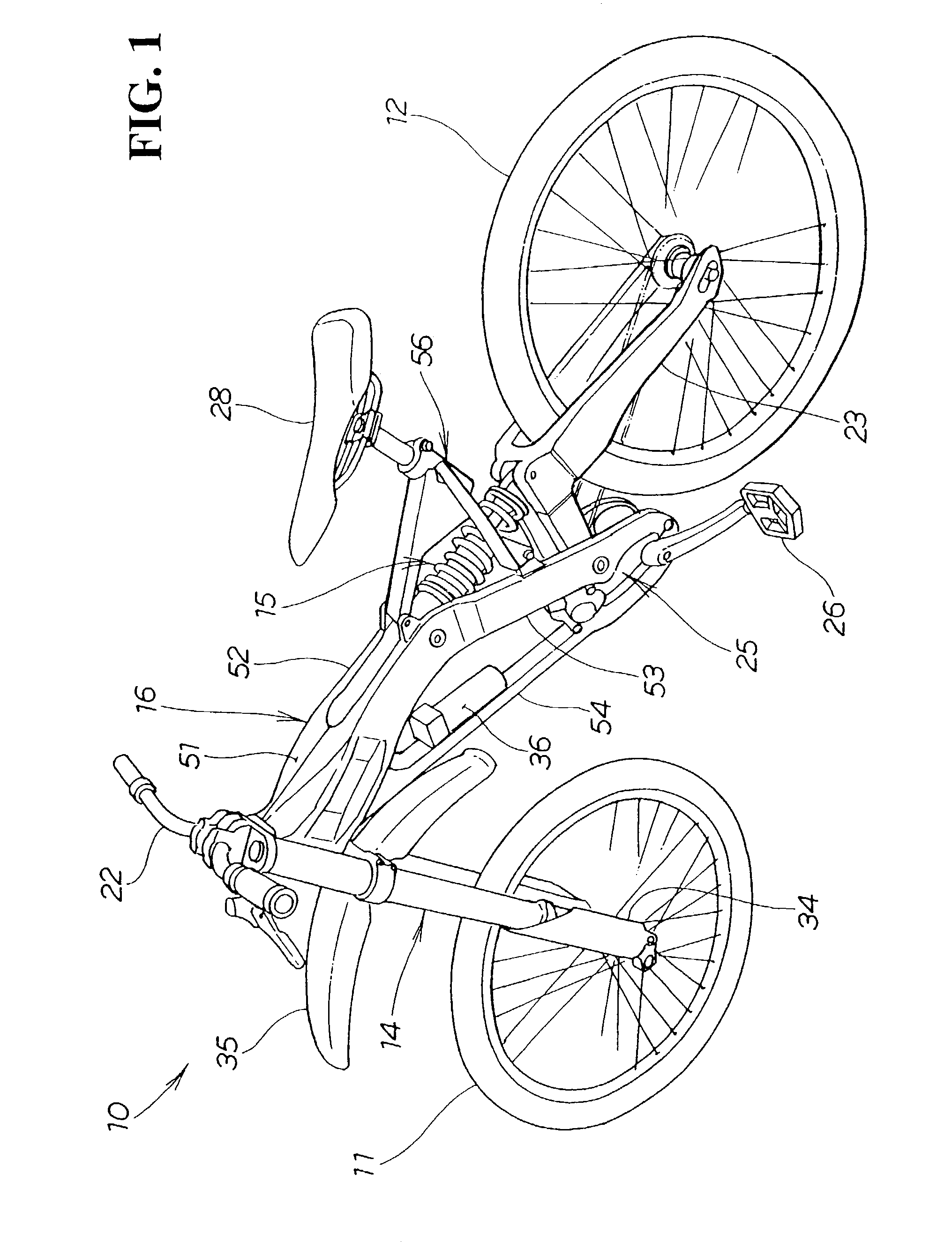
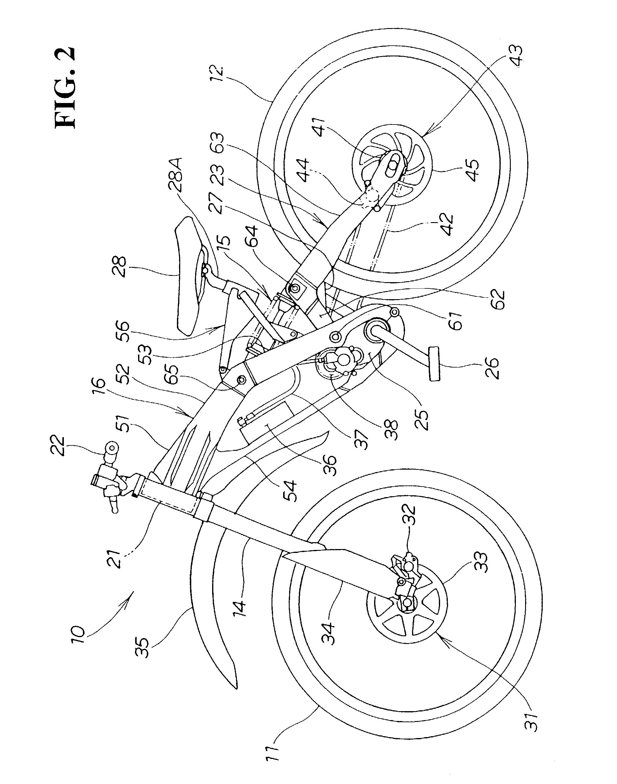
[0033]FIG. 1 is a perspective view of a bicycle having a body frame structure according to an embodiment of the present invention. FIG. 2 is a side view of the bicycle according to an embodiment of the present invention. FIG. 3 is a perspective view of a body frame according to an embodiment of the present invention. FIG. 4 is a plan view as viewed in the direction of an arrow 4 shown in FIG. 3. FIG. 5 is a side view showing the body frame structure according to an embodiment of the present invention. FIG. 6 is a side view showing portions of the body frame according to an embodiment of the present invention. FIG. 7 is a perspective view showing a lower portion of the body frame according to the present invention. FIG. 8 is a rear view of a rear portio...


PUM


Abstract

A body frame for a vehicle includes a head pipe on which a front fork is mounted for permitting a turning movement. A box-shaped box frame portion extends obliquely rearward and downwards from the head pipe. A twin tube portion extends obliquely downward and rearward on the left and right sides from a rear end of the box frame portion. The twin tube portion has a smaller width than the width of the box frame portion. A rear frame portion extending obliquely rearward and downward from the rear ends of the twin tube portion has a greater width than the width of the twin tube portion. Accordingly, the body frame can be formed such that it has a high rigidity in the proximity of the head pipe but has a low rigidity at a central portion of the body. Accordingly, a load transmitted from the road surface to the head pipe through the front wheel and the box frame portion can support the front fork. Further, since the rear frame portion is formed with an increased width, twisting of the swing arm can be reduced the steering of the vehicle is improved.

Description

CROSS-REFERENCES TO RELATED APPLICATIONS[0001]This nonprovisional application claims priority under 35 U.S.C. § 119(a) on Patent Application No. 2002-119426 filed in Japan on Apr. 22, 2002, the entirety of which is herein incorporated by reference.BACKGROUND OF THE INVENTION[0002]1. Field of the Invention[0003]The present invention relates to a body frame structure for a bicycle, and more particularly to a body frame structure suitable to augment the steering performance of the vehicle and support a high load applied to the body frame.[0004]2. Description of the Background Art[0005]Body frame structures for a bicycle, such as those described in (1) the official gazette of Japanese Patent Laid-open No. Hei 9-263282 “Bicycle Frame with a Buffer Apparatus” and (2) the official gazette of Japanese Patent Publication No. Hei 4-43834 “Frame for a Motorcycle,” have been available in the background art.[0006]In FIG. 1 of document (1) mentioned hereinabove, a triangular frame is disclosed wh...

Claims


Application Information

Patent Timeline
IPC IPC(8): B62K3/10B62K11/02B62K19/18B62K25/10B62K25/28
CPCB62K3/10B62K25/28
Inventor MORITA, KENJI
Owner HONDA MOTOR CO LTD
Features
  • R&D
  • Intellectual Property
  • Life Sciences
  • Materials
  • Tech Scout
  • Unparalleled Data Quality
  • Higher Quality Content
  • 60% Fewer Hallucinations
Learn More