Backlight unit

a backlight unit and backlight technology, applied in lighting and heating apparatus, planar/plate-like light guides, instruments, etc., can solve the problems of narrow operation temperature range, high frequency ac signal of ccfl, image displayed on liquid crystal display cannot be viewed in a dark place, etc., to achieve the effect of improving brightness uniformity

Active Publication Date: 2005-12-27
SAMSUNG ELECTRONICS CO LTD
View PDF7 Cites 49 Cited by
  • Summary
  • Abstract
  • Description
  • Claims
  • Application Information

AI Technical Summary

Benefits of technology

[0015]To solve the above and other problems, the present invention provides an edge light backlight unit which can improve uniformity in brightness at a light exhaust surface by decreasing an azimuth angle of light emitted from a point light source to be incident on a light guide panel.

Problems solved by technology

Since the liquid crystal display does not form an image by emitting light by itself, but forms an image by receiving light from the outside, the image displayed on the liquid crystal display cannot be viewed in a dark place.
However, it is disadvantageous in that the CCFL is operated by a high frequency AC signal and an operational temperature range is narrow.
Compared to the CCFL in brightness and homogeneity, the LED does not perform as well.

Method used


Image

  • Backlight unit
  • Backlight unit
  • Backlight unit

Examples


Embodiment Construction

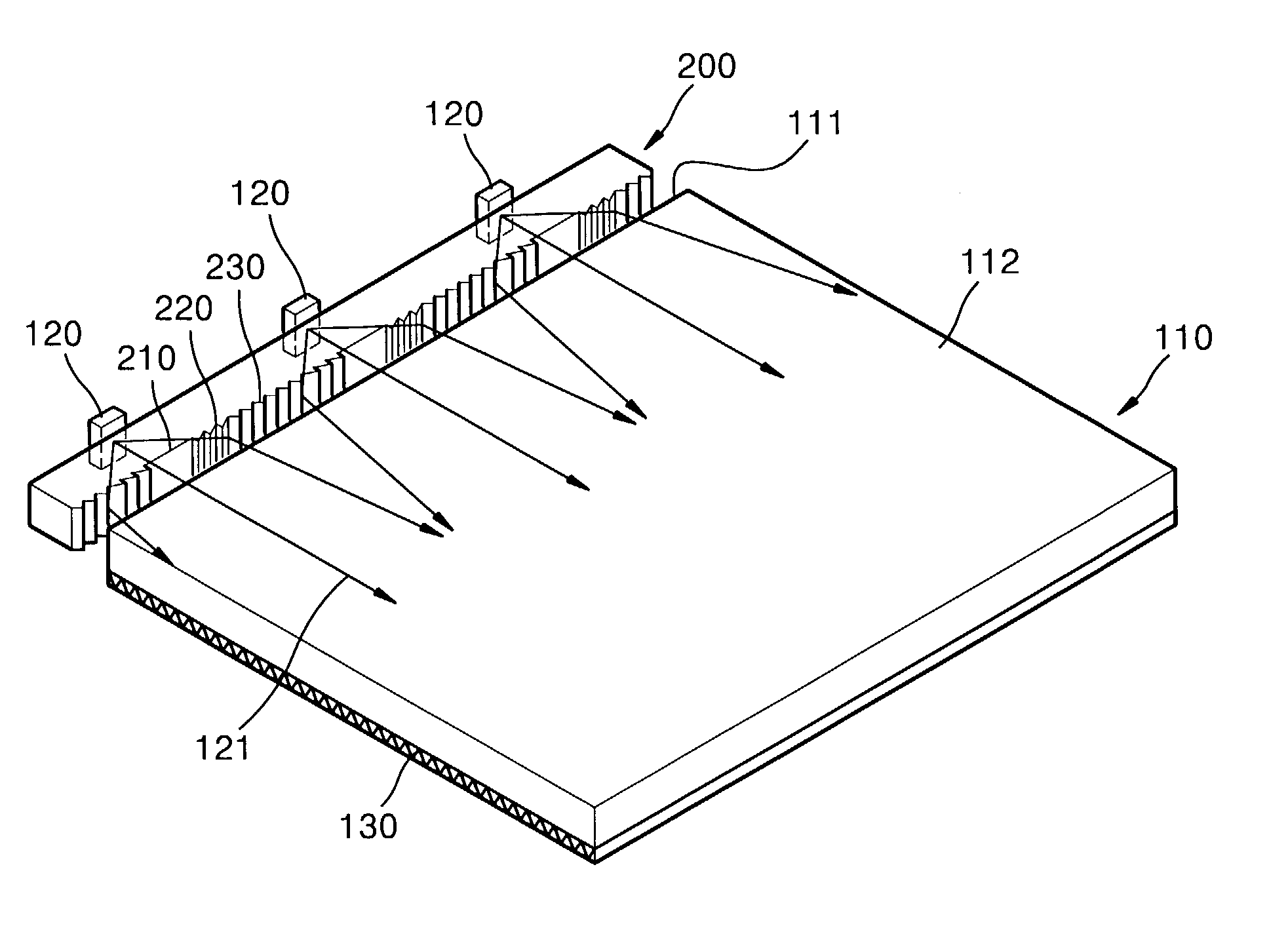
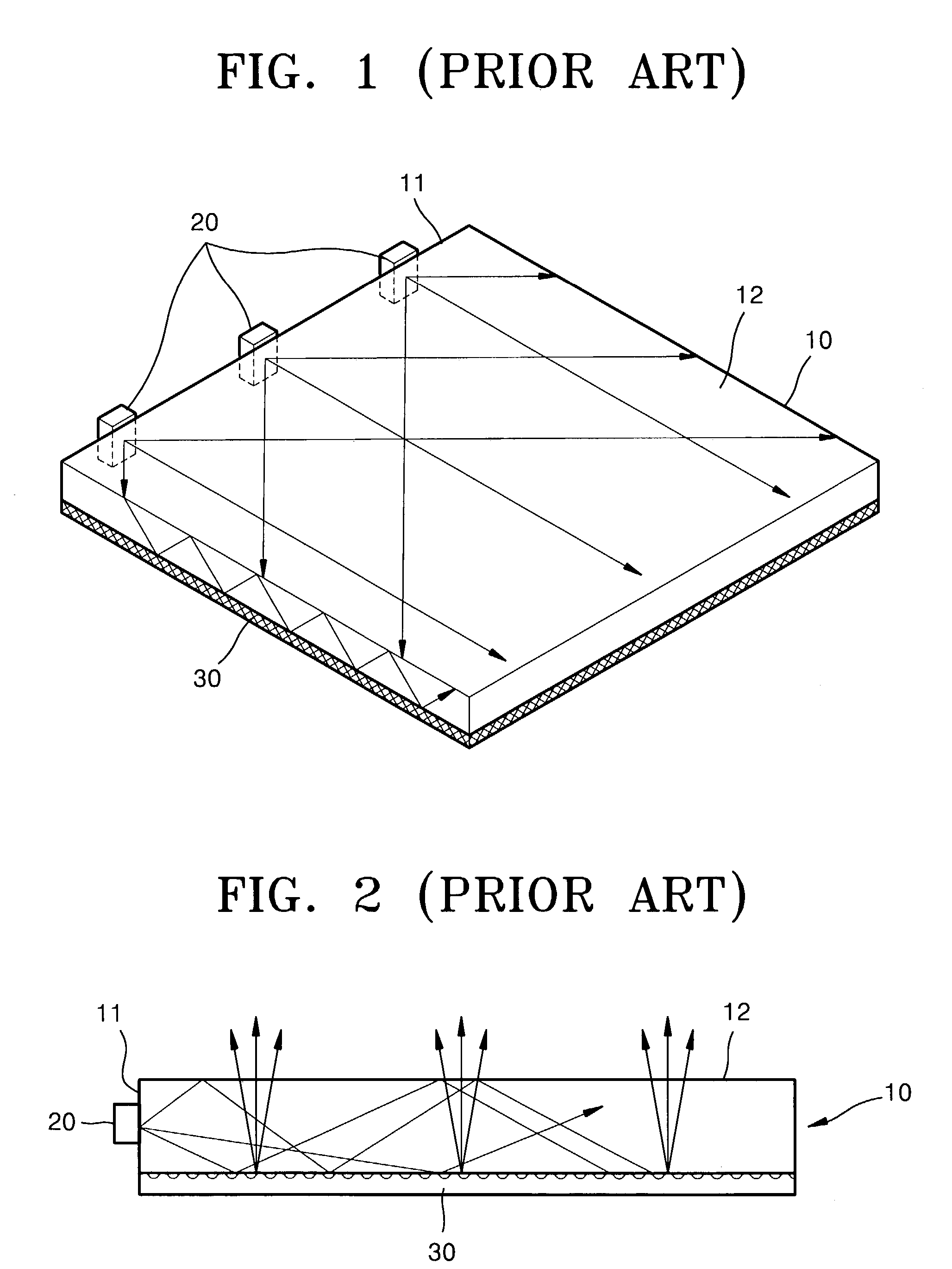
[0037]Referring to FIG. 6, three LEDs 120 are installed at an edge 111 of a light guide panel 110 as point light sources. A refractive member 200 is installed between the light guide panel 110 and the LEDs 120. For example, a material such as air having a refractive index lower than the refractive member 200 or a part of the light guide panel 110 is provided between the LEDs 120 and the refractive member 200, and between the refractive member 200 and the light guide panel 110.

[0038]The light guide panel 110 is manufactured of a material capable of transmitting light. As the light transmitting material, acrylic transparent resin (PMMA) having a refractive index of about 1.49 and a specific gravity of about 1.19 is mainly used. For light weight, an olefin based transparent resin having a specific gravity of about 1.0 is used. The light guide panel 110 is normally about 2–3 mm thick and a wedge type design having a thickness gradually decreasing from an incident portion to a far portio...


PUM

PropertyMeasurementUnit
azimuth angleaaaaaaaaaa
azimuth anglesaaaaaaaaaa

Abstract

A backlight unit includes a light guide panel where a holographic pattern is formed. A point light source emits light to an edge of the light guide panel. A refractive member is provided between the point light source and the light guide panel and reduces an azimuth angle of light incident on the light guide panel. The refractive member includes, from an optical axis of the point light source, a light transmission zone transmitting light as it is, a blaze zone where a blaze pattern having a saw-toothed shape in which one surface near the optical axis and substantially parallel to the optical axis is formed, and a prism zone where a triangular prism pattern is formed. The backlight unit may further include a diffusive member diffusing light emitted from the point light source to be incident on the refractive member.

Description

BACKGROUND OF THE INVENTION[0001]This application claims the priority of Korean Patent Application No. 2003-780 filed on Jan. 7, 2003, in the Korean Intellectual Property Office, the disclosure of which is incorporated herein in its entirety by reference.[0002]1. Field of the Invention[0003]The present invention relates to a backlight unit, and more particularly, to an edge light backlight unit using a light guide panel (LGP) and a point light source.[0004]2. Description of the Related Art[0005]Typically, flat displays are classified into light emission types and light receiving types. An example of a light receiving type flat display is a liquid crystal display. Since the liquid crystal display does not form an image by emitting light by itself, but forms an image by receiving light from the outside, the image displayed on the liquid crystal display cannot be viewed in a dark place. Thus, a backlight unit for emitting light is installed on a rear surface of the liquid crystal displ...

Claims


Application Information

Patent Timeline
Patent Type & Authority Patents(United States)
IPC IPC(8): F21V8/00G02B6/00F21Y101/02G02B5/02G02B5/32G02B27/09G02F1/13357
CPCG02B6/0016G02B6/003G02B27/0972G02F1/1335
Inventor MIN, JEE-HONGCHOI, HWAN-YOUNGLEE, MOON-GYULEE, SU-MIKIM, JIN-HWANCHOI, JIN-SEUNG
Owner SAMSUNG ELECTRONICS CO LTD
Why Eureka
Try Eureka