Arrangement for an exhaust gas turbo charger with a carrier housing

a carrier housing and exhaust gas turbo charger technology, which is applied in the direction of liquid fuel engines, positive displacement liquid engines, piston pumps, etc., can solve the problems of poor access to the screw heads during assembly, and achieve the effect of reducing the total space required for construction of the exhaust gas turbo charger, facilitating screw connection, and assembling within a short tim

Active Publication Date: 2005-12-27
ROLLS ROYCE SOLUTIONS GMBH
View PDF13 Cites 20 Cited by
  • Summary
  • Abstract
  • Description
  • Claims
  • Application Information

AI Technical Summary

Benefits of technology

[0007]Thanks to better accessibility of the screw connection, the bearing housing can be assembled within a short time. The distance between the compressor housing and the turbine housing is shorter than that known from prior art; in other words, the total space required for construction of the exhaust gas turbo charger is reduced. An additional effect involves the fact that the bearing housing can be in a form which involves a simple construction.
[0008]By means of an ancillary centering device, the assembly time of the arrangement is shortened. The ancillary centering device is in the form of a snap-on contact. This, first of all, permits the exhaust gas turbo charger and the carrier housing to be oriented, relative to each other, in the direction of the shaft, and, secondly, permits the lubricant to be conducted out of the bearing housing into the carrier housing.
[0009]In contrast to what is known from the prior art, there is no longer any need for the contact surface produced by the axial screw connection and sealing to the carrier housing. This has the effect of taking away less heat from the exhaust gas; in other words, the enthalpy of the exhaust gas is improved.

Problems solved by technology

Another problem with this arrangement involves the poor accessibility of the screw heads during assembly.

Method used


Image

  • Arrangement for an exhaust gas turbo charger with a carrier housing
  • Arrangement for an exhaust gas turbo charger with a carrier housing
  • Arrangement for an exhaust gas turbo charger with a carrier housing

Examples


Embodiment Construction

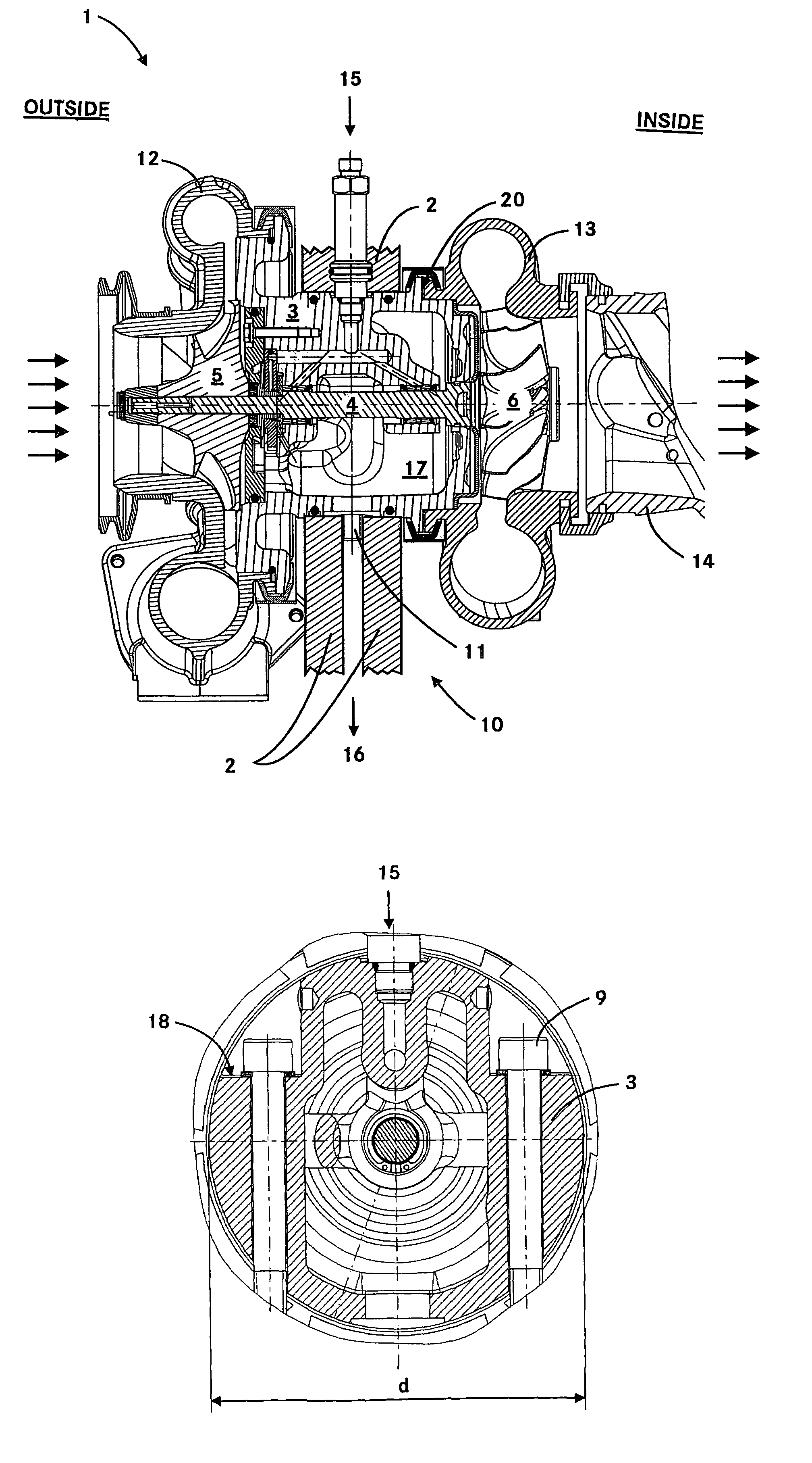
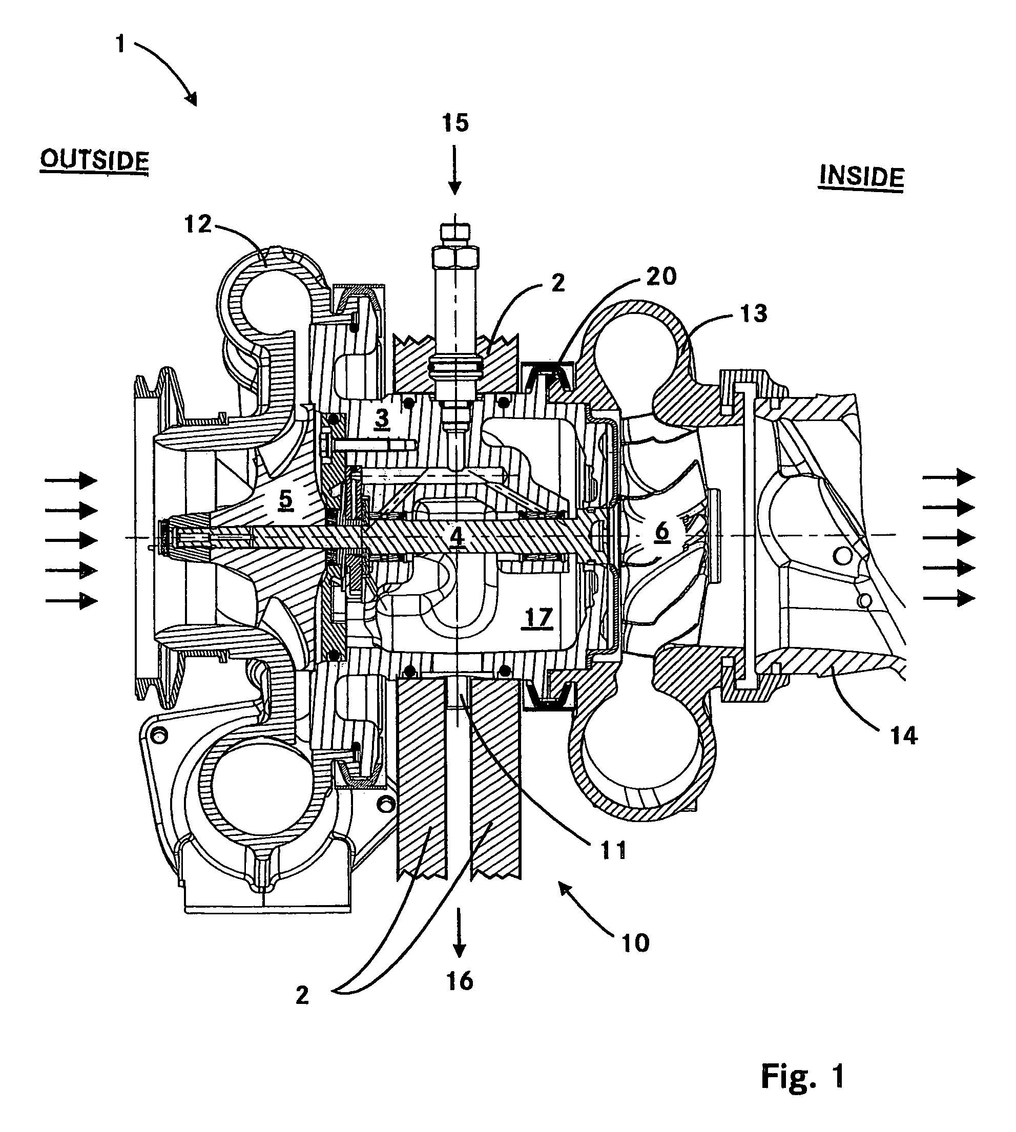
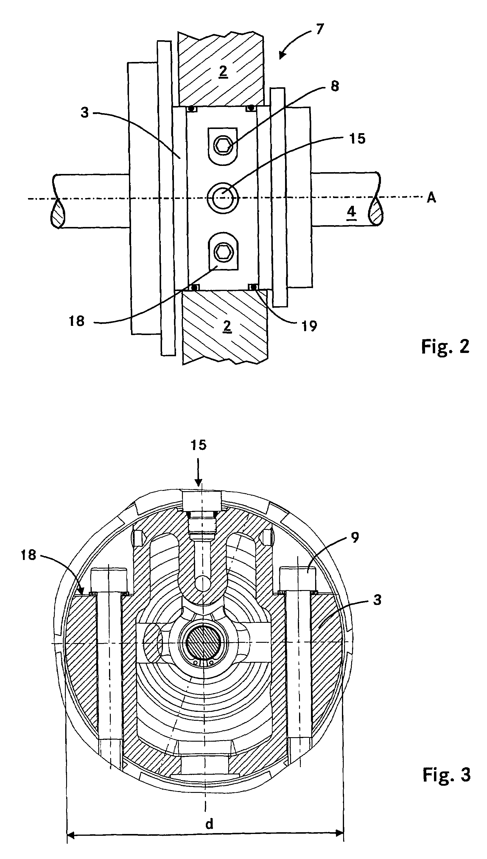
[0014]FIG. 1 represents a cutaway view of the arrangement of an exhaust gas turbo charger 1 with a carrier housing 2. The function of an exhaust gas turbo charger 1, in the text which follows, is presumed to be known. In a manner known from prior art, an exhaust gas turbo charger comprises a compressor housing 12 with a compressor wheel 5, a turbine housing 13 with a turbine wheel 6 and a bearing housing 3. Arranged within the bearing housing 3 is a shaft 4. By means of the shaft 4, the compressor wheel 5 and the turbine wheel 6 are connected to each other in a torque-proof manner. The turbine housing 13 with an exhaust gas line 14 is located within the carrier housing 2. The compressor housing 12 is located outside the carrier housing 2. As shown in FIG. 1, the air inlet takes place in the direction shown in the drawing, from the left, and the exhaust gas outlet takes place in the direction shown in the drawing, toward the right. By means of a supply inlet 15, lubricant is supplied...


PUM


Abstract

An arrangement is proposed for an exhaust gas turbo charger with a carrier housing. The exhaust gas turbo charger is attached to a bearing housing with the carrier housing by way of a fastening element such that the fastening element is oriented in a direction perpendicular to a shaft arranged within the bearing housing.

Description

[0001]This application claims the priority of German application 103 11 996.5, filed Mar. 19, 2003, the disclosure of which is expressly incorporated by reference herein.BACKGROUND AND SUMMARY OF THE INVENTION[0002]This invention concerns an arrangement for an exhaust gas turbo charger with a carrier housing in which the exhaust gas turbo charger includes a compressor wheel, a turbine wheel, a bearing housing, and a shaft adapted to connect the compressor wheel and the turbine wheel.[0003]An arrangement for an exhaust gas turbo charger with a carrier housing is known from German publication DE 34 39 738 C2. In a manner known from prior art, an exhaust gas turbo charger comprises a compressor housing with a compressor wheel, a turbine housing with a turbine wheel and a bearing housing with a shaft for connection of the compressor wheel to the turbine wheel. The exhaust gas turbo charger and the carrier housing are screwed together. The screws are arranged in an axial direction, that ...

Claims


Application Information

Patent Timeline
Patent Type & Authority Patents(United States)
IPC IPC(8): F01D25/28F02C6/12F04D25/04F04D29/62
CPCF01D25/28F02C6/12F04D25/04F04D29/624F05D2250/313F05D2220/40
Inventor BAUMANN, HERMANN
Owner ROLLS ROYCE SOLUTIONS GMBH
Why Eureka
Try Eureka