
Electrical connector having a mechanism for supplementing spring characteristics of a contact

a technology of electric connectors and spring characteristics, applied in the direction of coupling contact members, coupling device connections, coupling/disassembly parts, etc., can solve the problems of reducing and reducing the size of the contact, so as to improve the reliability of the contact

Inactive Publication Date: 2005-12-27
JAPAN AVIATION ELECTRONICS IND LTD +1
View PDF20 Cites 26 Cited by
  • Summary
  • Abstract
  • Description
  • Claims
  • Application Information

AI Technical Summary

Benefits of technology

[0005]It is therefore an object of this invention to provide an electrical connector which is capable of supplementing spring characteristics of a contact so as to improve a contact reliability of the contact even if the contact is reduced in size.
[0006]It is another object of this invention to provide an electrical connector which is easy to make design change for adjusting spring characteristics of a contact and to carry out replacement of parts.

Problems solved by technology

However, if the electrical connector is reduced in size, the contact is also miniaturized.
It is therefore difficult to provide the contact with sufficient spring characteristics.
This results in permanent deformation of the contact or insufficiency in contact force, thereby decreasing a contact reliability.

Method used


Image

  • Electrical connector having a mechanism for supplementing spring characteristics of a contact
  • Electrical connector having a mechanism for supplementing spring characteristics of a contact
  • Electrical connector having a mechanism for supplementing spring characteristics of a contact

Examples


Embodiment Construction

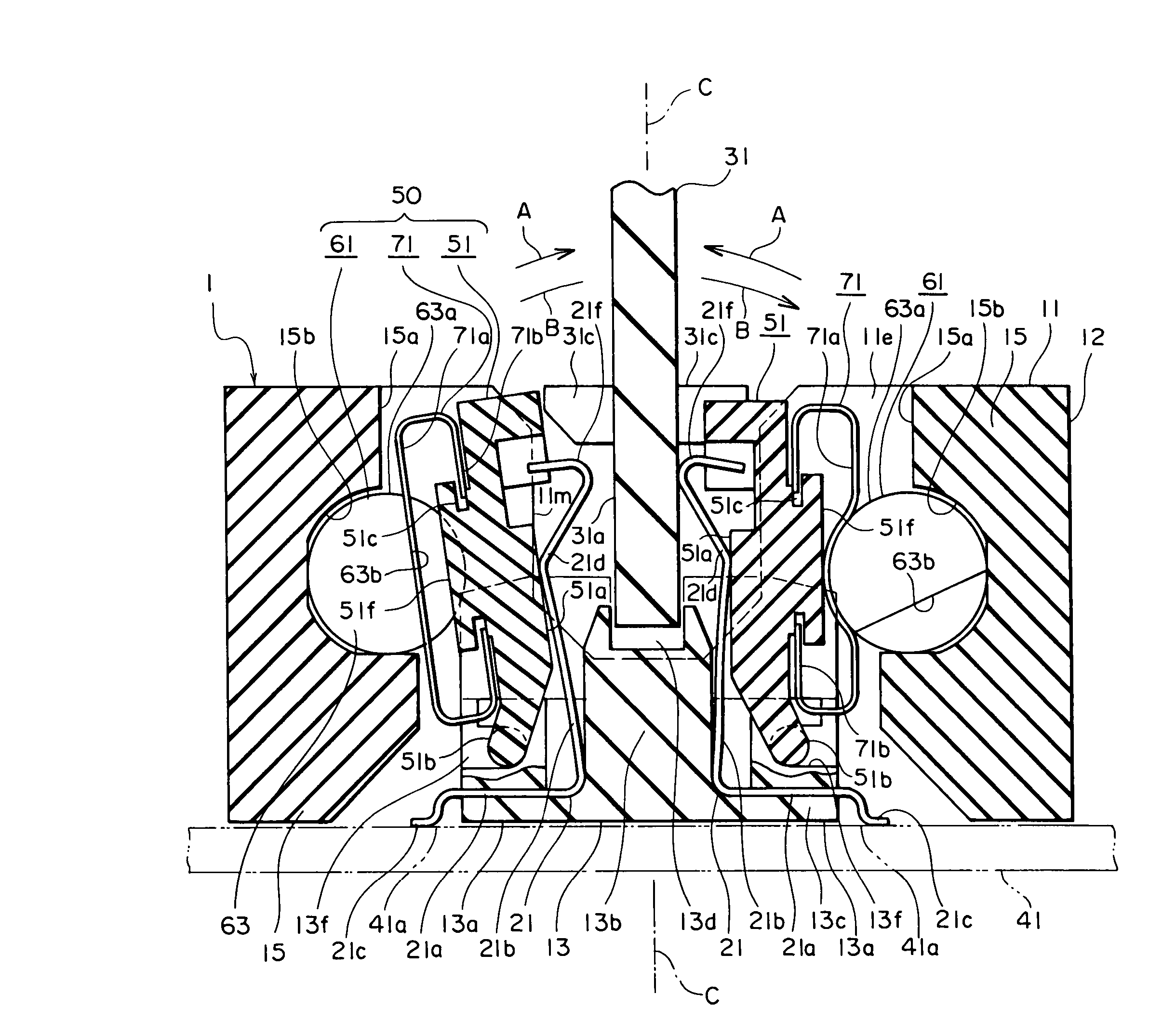
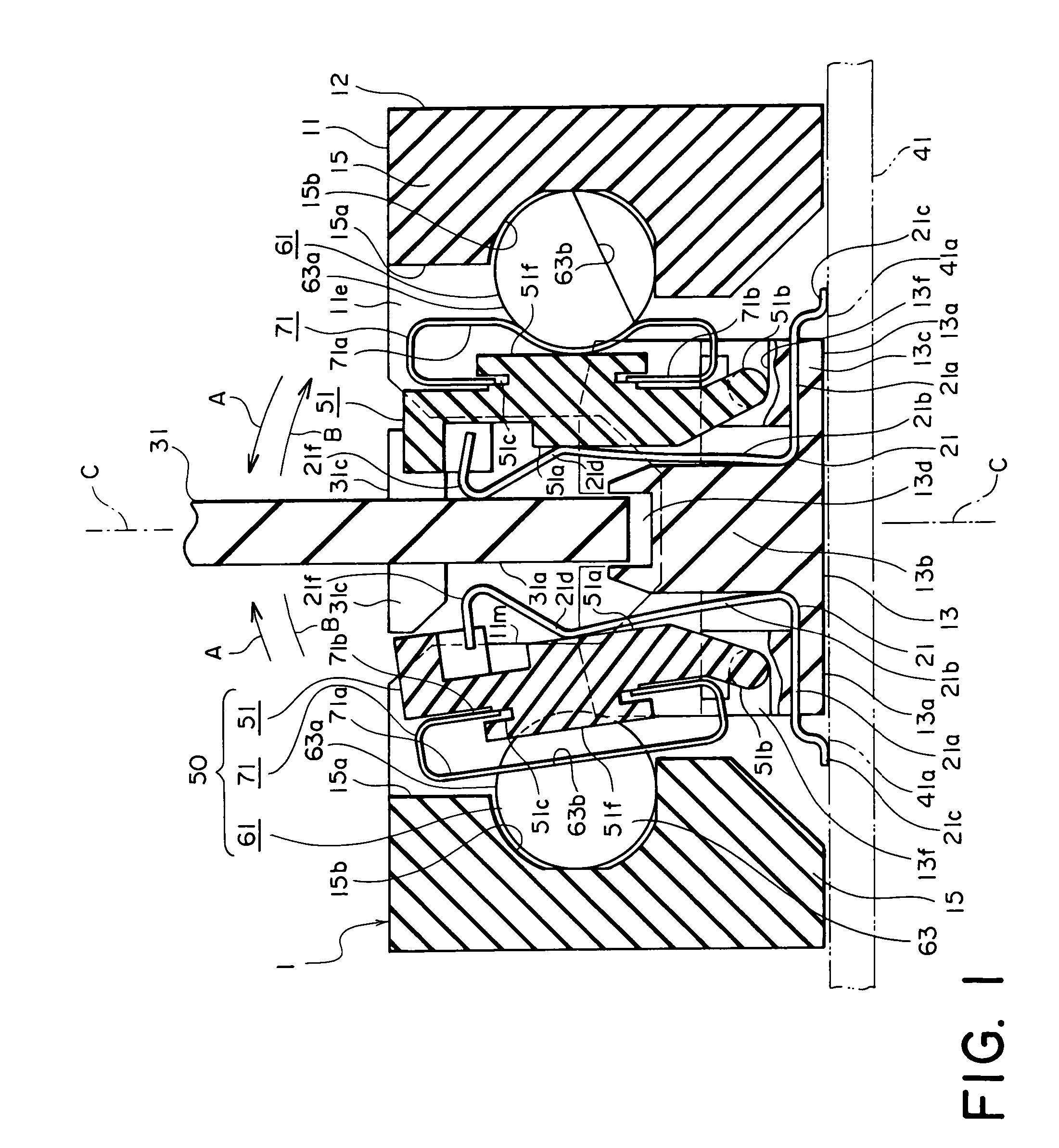
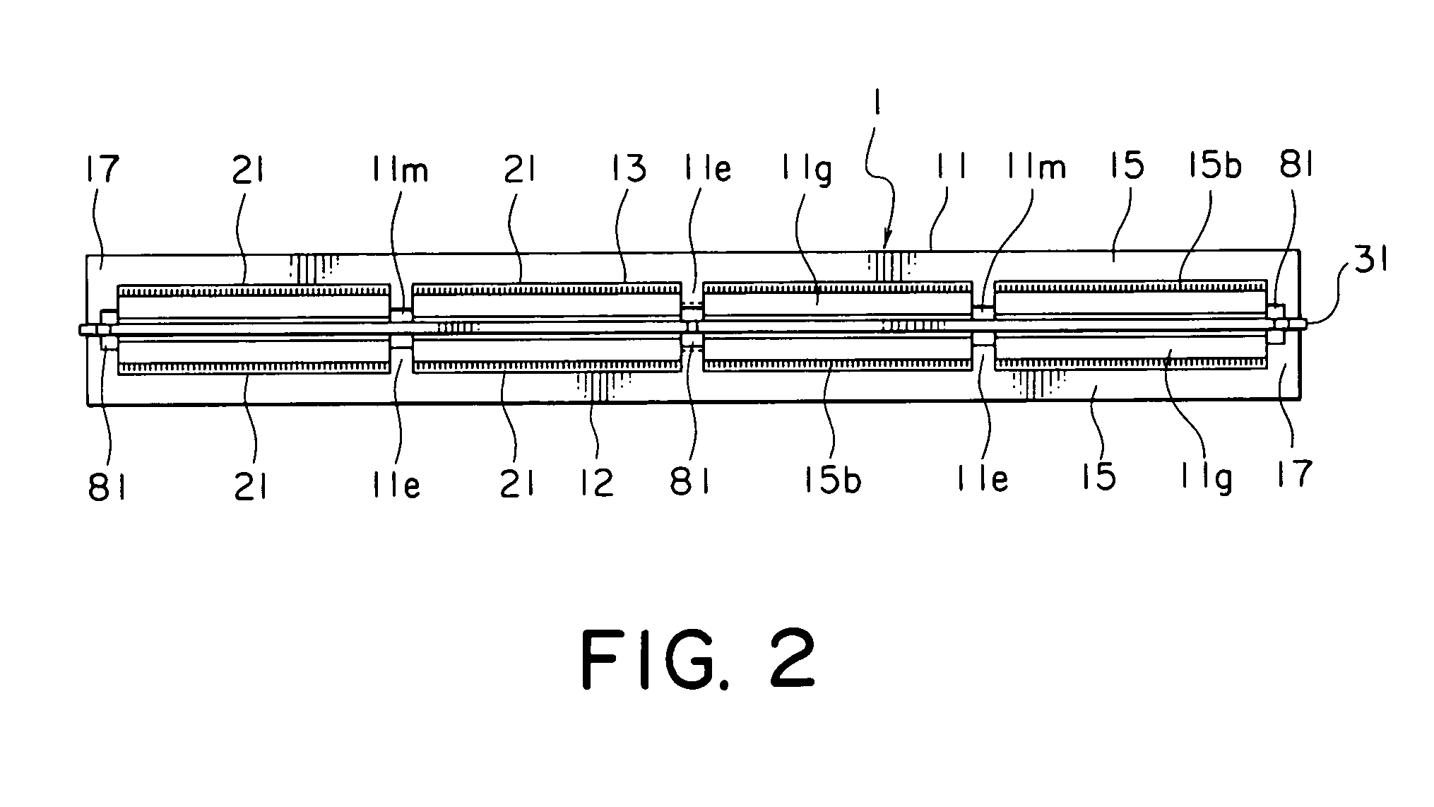
[0015]Referring to FIGS. 1 through 3, description will be made of an electrical connector according to one embodiment of this invention.

[0016]The electrical connector 1 illustrated in the figure is generally called a card-edge electrical connector and comprises an insulating housing 11, a plurality of conductive contacts 21 disposed within the housing 11, and a plurality of contact moving mechanisms 50 coupled to the housing 11.

[0017]The housing 11 comprises a frame member 12 and a plurality of (four in the illustrated example) header members 13 fixed to the frame member 12 and aligned in a single line. The frame member 12 has a pair of first frame portions 15 extending in a longitudinal direction of the housing 11 and facing the header members 13 with a space kept therefrom in a transversal direction of the housing 11, and a pair of second frame portions 17 connecting longitudinal opposite ends of the first frame portions 15. Thus, a combination of the first and the second frame po...


PUM


Abstract

In a connector comprising a housing (11) and a contact (21) held by the housing, the contact is brought into contact with a connection object under a pressing force obtained by operating an operating member (61). An elastic member (71) elastically deformable is interposed between the contact and the operating member. The operating member has a first cam surface (63a) for applying the pressing force to the contact with elastic deformation of the elastic member and a second cam surface (63b) for releasing the pressing force. An insulating actuator (51) cooperating with the contact may be interposed between the contact and the elastic member. The elastic member may be a leaf spring member held by the actuator.

Description

[0001]This invention claims priority to prior Japanese patent application JP 2003-134207, the disclosure of which is incorporated herein by reference.BACKGROUND OF THE INVENTION[0002]This invention relates to an electrical connector for connecting a substrate as a mother board and a connection object as a daughter board.[0003]For example, Japanese Patent Application Publication (JP-A) No. H6-196230 (corresponding to U.S. Pat. No. 5,273,450) discloses an electrical connector for connecting a mother board and a daughter board. The electrical connector comprises a connector body mounted on the mother board, and a compressible connector element carried by the connector body. The daughter board is inserted into the connector body and disposed to be substantially perpendicular to the mother board. The daughter board is provided with a circuit element to be electrically connected to the connector element. The connector element is used as a contact for electrically connecting the mother boa...

Claims


Application Information

Patent Timeline
IPC IPC(8): H01R24/00
CPCH01R12/88H01R12/721
Inventor MAEDA, TOSHIHIKOTAKAHASHI, ISAO
Owner JAPAN AVIATION ELECTRONICS IND LTD
Learn More