
Pipe bundle for underground installation

a pipe bundle and underground installation technology, applied in special purpose vessels, electrical apparatus casings/cabinets/drawers, coupling device connections, etc., can solve problems such as potentially larger conduit groups, and achieve the effects of reducing the force acting on pipes, reducing the size of pipes, and optimizing the electrical/magnetic characteristics of the design

Inactive Publication Date: 2005-12-27
ENTERGY LOUSNA
View PDF39 Cites 45 Cited by
  • Summary
  • Abstract
  • Description
  • Claims
  • Application Information

AI Technical Summary

Benefits of technology

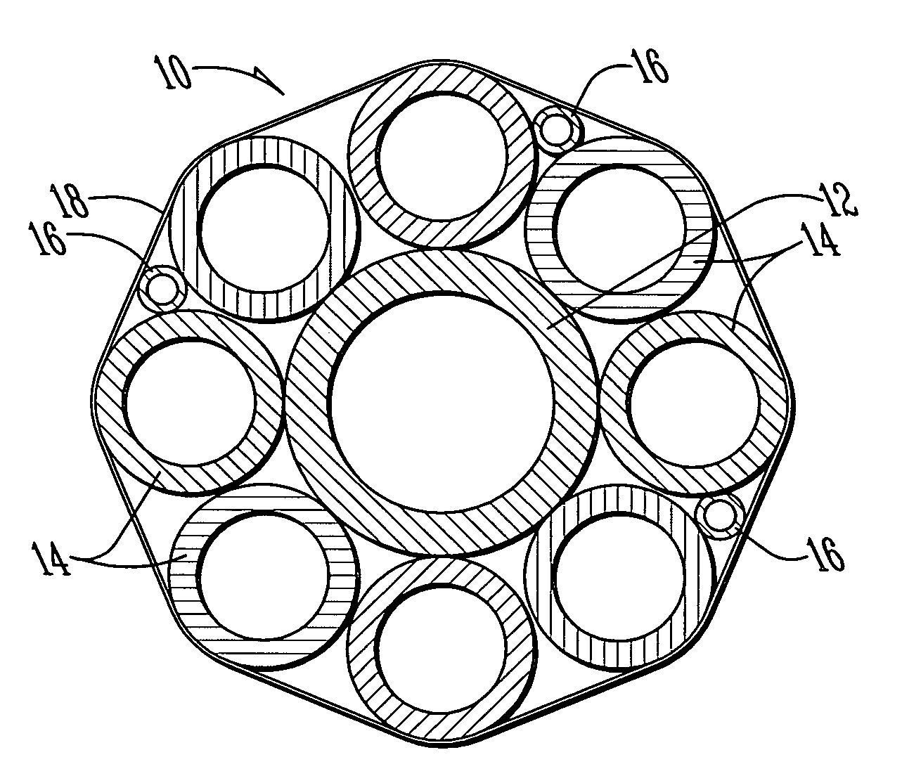
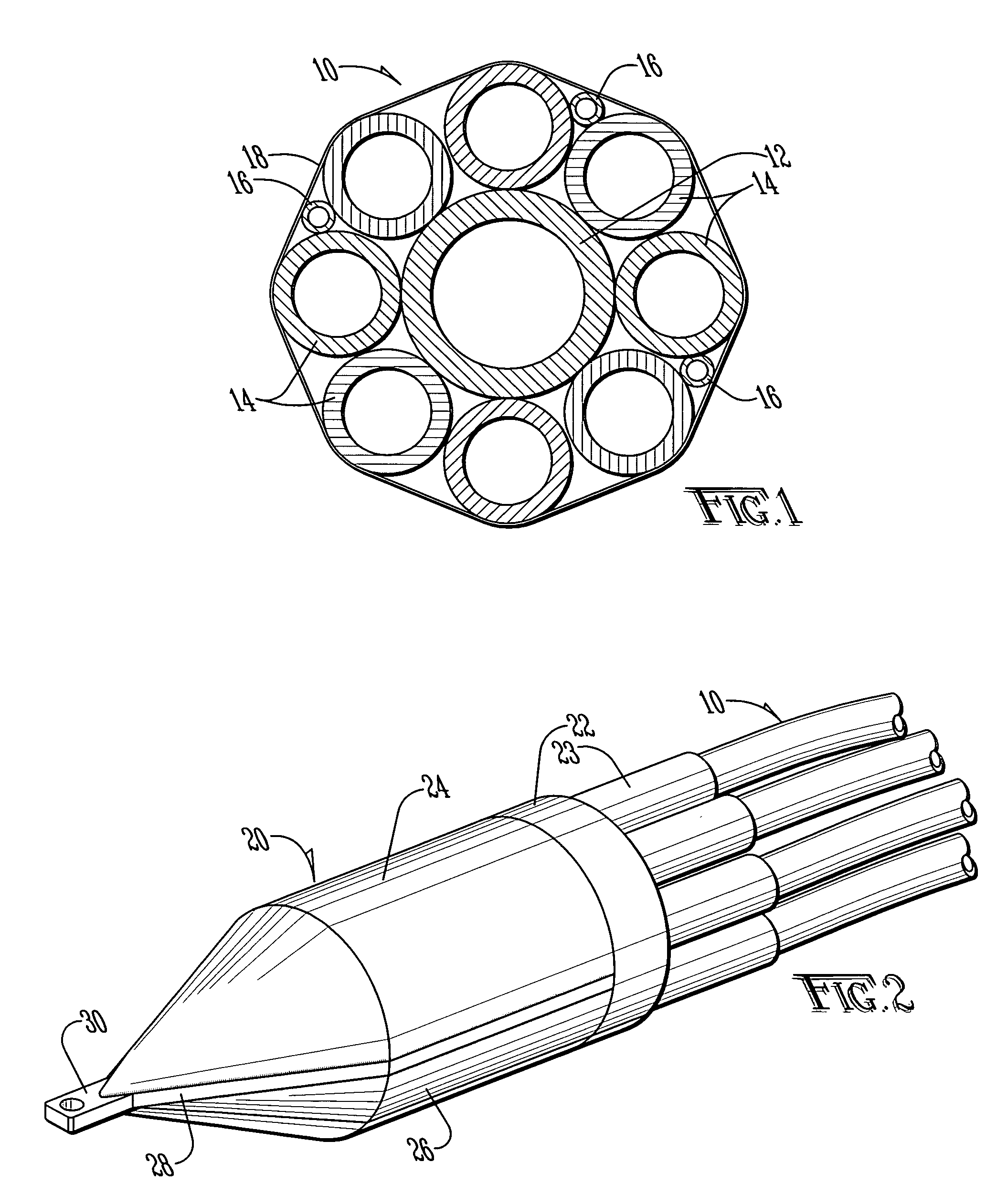
[0018]The present invention is directed to a pipe bundle for use as conduits to carry cables through a wellbore. The pipes forming the bundle are of varying size and of a configuration so as to form a bundle that can withstand the forces related to installation in a wellbore, while including conduits of large size as required for certain applications and optimizing the electrical / magnetic characteristics of the design. In addition, the pipes are formed into a bundle by bindings periodically placed along their length so that the bundle moves and deflects as a single unit, similar to a bundle fitted into a casing. The bundling is also an aspect of the invention that reduces the forces acting on the pipes during installation. This configuration results in a group of conduits of potentially larger size, and which may be pulled through a longer wellbore to accommodate larger crossing requirements. Because no outer casing is required in this bundle configuration, the cost of installing the conduits is significantly reduced. Furthermore, since no outer casing is required, the problems related to heat dissipation or electrical / conduction issues related to the use of metal conduits are eliminated.
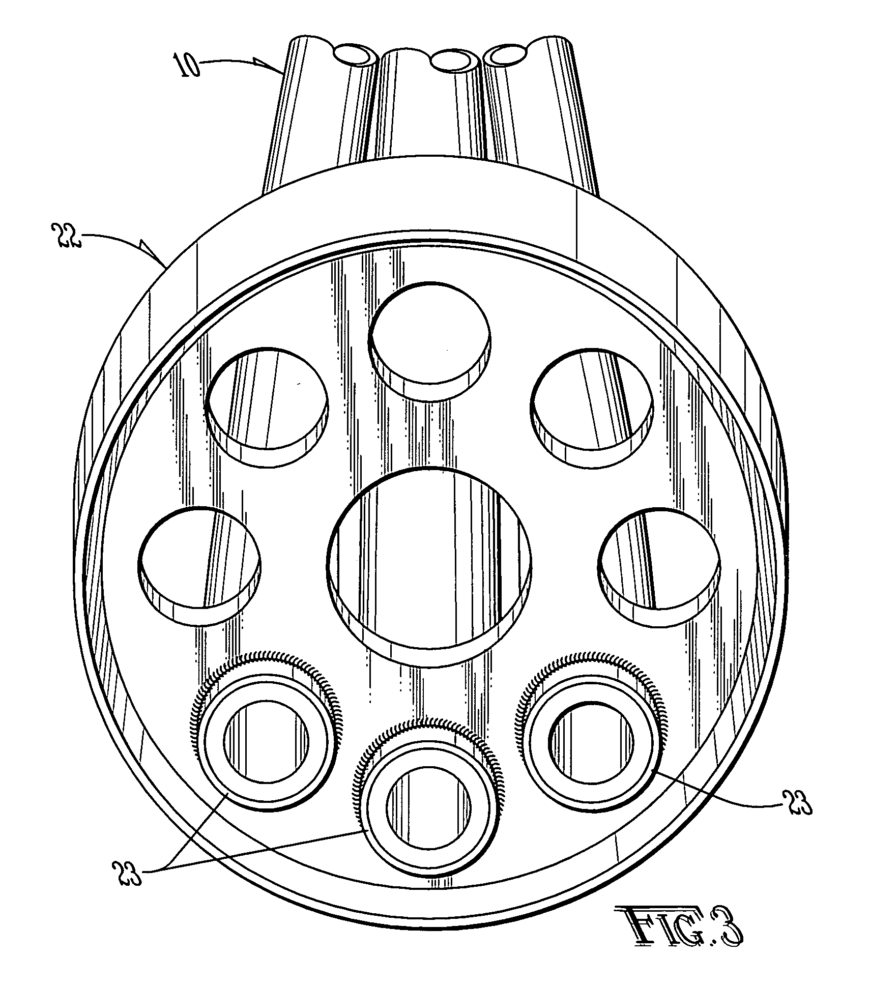
[0019]The present invention is further directed to a pulling head that may be attached to the conduit bundle that allows the bundle to be more easily pulled through the wellbore without undue stress on the bundle. The pulling head is designed to receive a bundle in a particular configuration. In addition, the pulling head allows for the flow of a weighting material through all of the conduits by forming a reservoir connecting all of the conduits in a fluidic fashion. The use of a weighting material reduces the force upon the bundle during installation because it prevents the buoyancy of the conduit from creating additional pressure between the top of the bundle and the top of the wellbore.

Problems solved by technology

This configuration results in a group of conduits of potentially larger size, and which may be pulled through a longer wellbore to accommodate larger crossing requirements.

Method used


Image

  • Pipe bundle for underground installation
  • Pipe bundle for underground installation
  • Pipe bundle for underground installation

Examples


Embodiment Construction

[0034]In the preferred embodiment, an HDPE pipeline bundle is installed through an HDD-created wellbore passing underneath a body of water or other obstacle. The preferred embodiment has been applied in the installation of a pipe bundle under a large river; this bundle was designed for use as conduit for both power transmission and communications cables. More specifically, the problem to be solved in developing the preferred embodiment was the passage of two circuits of three-phase, high voltage (230 kV) electrical transmission lines under a large river. In addition, three fiber optic communications cables were to be installed through the passage. The wellbore in this particular case reached a depth of 196 feet below the eastern and western banks of the river, with a total pipeline length of 3,495 feet.

[0035]With reference to FIG. 1, the preferred embodiment of the present invention may be described. Bundle 10 is formed of various diameters of HDPE, extra-high molecular weight (EHMS...


PUM


Abstract

A pipe conduit bundle for installation into a wellbore using horizontal drilling techniques is disclosed. The pipe conduit does not require an outer casing for construction. The pipe bundle configuration is formed by pipes of varying sizes in a particular configuration, with bindings interspaced along the length of the pipes such that the pipe bundle deflects as a single unit during installation. A pulling head is attached to the bundle, which is hollow to allow liquid entering one pipe to be distributed to other pipes. Liquids such as water may be used to fill the pipes to reduce buoyancy, and thereby reduce drag, during installation of the bundle.

Description

BACKGROUND OF THE INVENTION[0001]The present invention relates to underground conduits, and specifically relates to multiple pipes used as conduits wherein the pipes are installed together without an outer casing.[0002]Transmission cables of various sorts are ubiquitous throughout the world's developed countries. Such cables include electrical power transmission lines as well as various types of communications cables, such as co-axial cable and fiber optic cable. When installed above ground, these cables will typically be carried along poles or towers in order to avoid contact between the cables and persons or objects at ground level. Above-ground installations are often not practical, however, in crowded urban environments. Above-ground installations also increase the risk that the cables will be damaged or destroyed, such as by falling trees or other objects, or by high winds or other weather-related causes. Finally, above-ground installations are generally considered unsightly, a...

Claims


Application Information

Patent Timeline
Patent Type & Authority Patents(United States)
IPC IPC(8): H02G1/06H02G1/08H02G3/04H02G9/06
CPCH02G1/06H02G1/081H02G9/06
Inventor ZIMMERMANN, PAUL MICHAEL
Owner ENTERGY LOUSNA
Learn More