Fuel feed apparatus having sub tank and jet pump
- Summary
- Abstract
- Description
- Claims
- Application Information
AI Technical Summary
Benefits of technology
Problems solved by technology
Method used
Image
Examples
first embodiment
[First Embodiment]
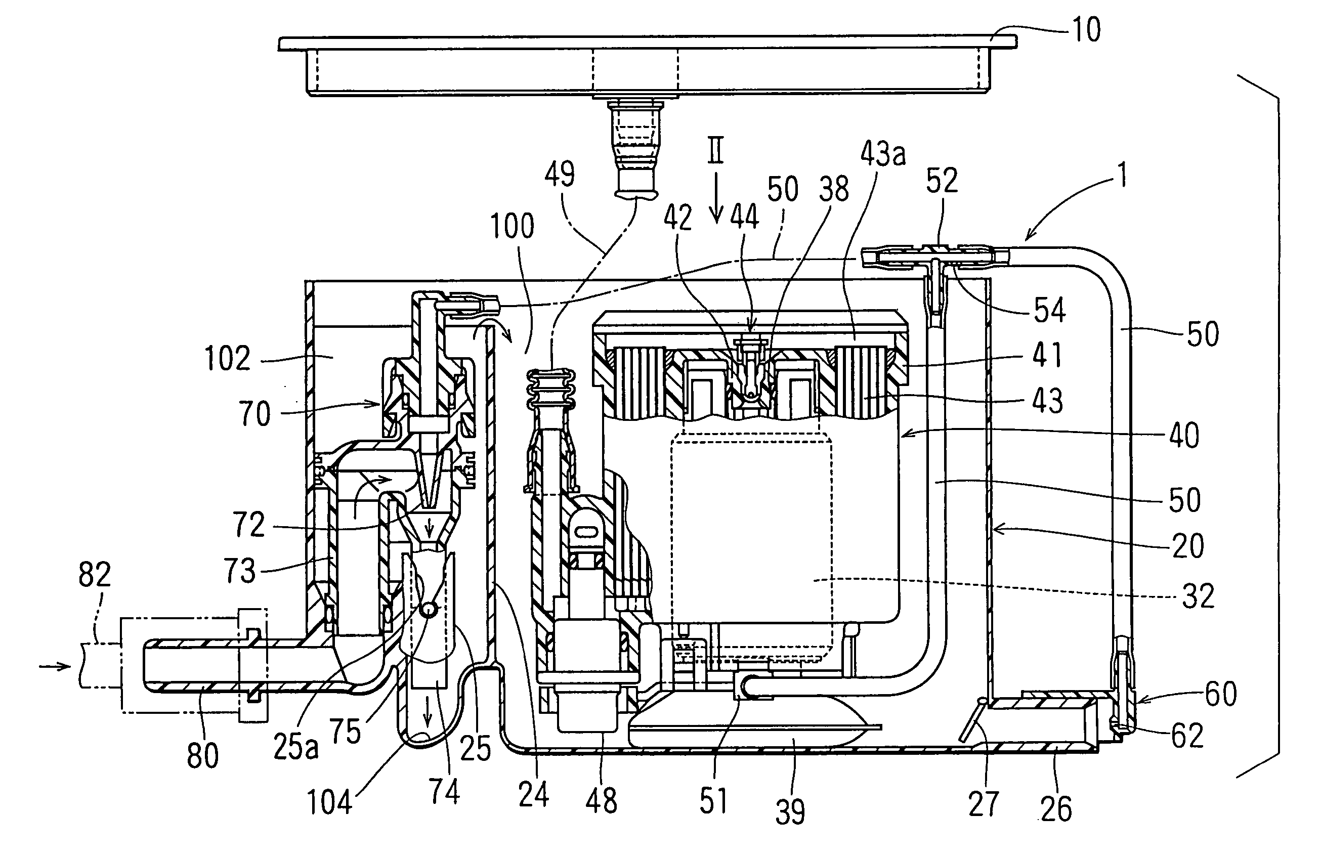
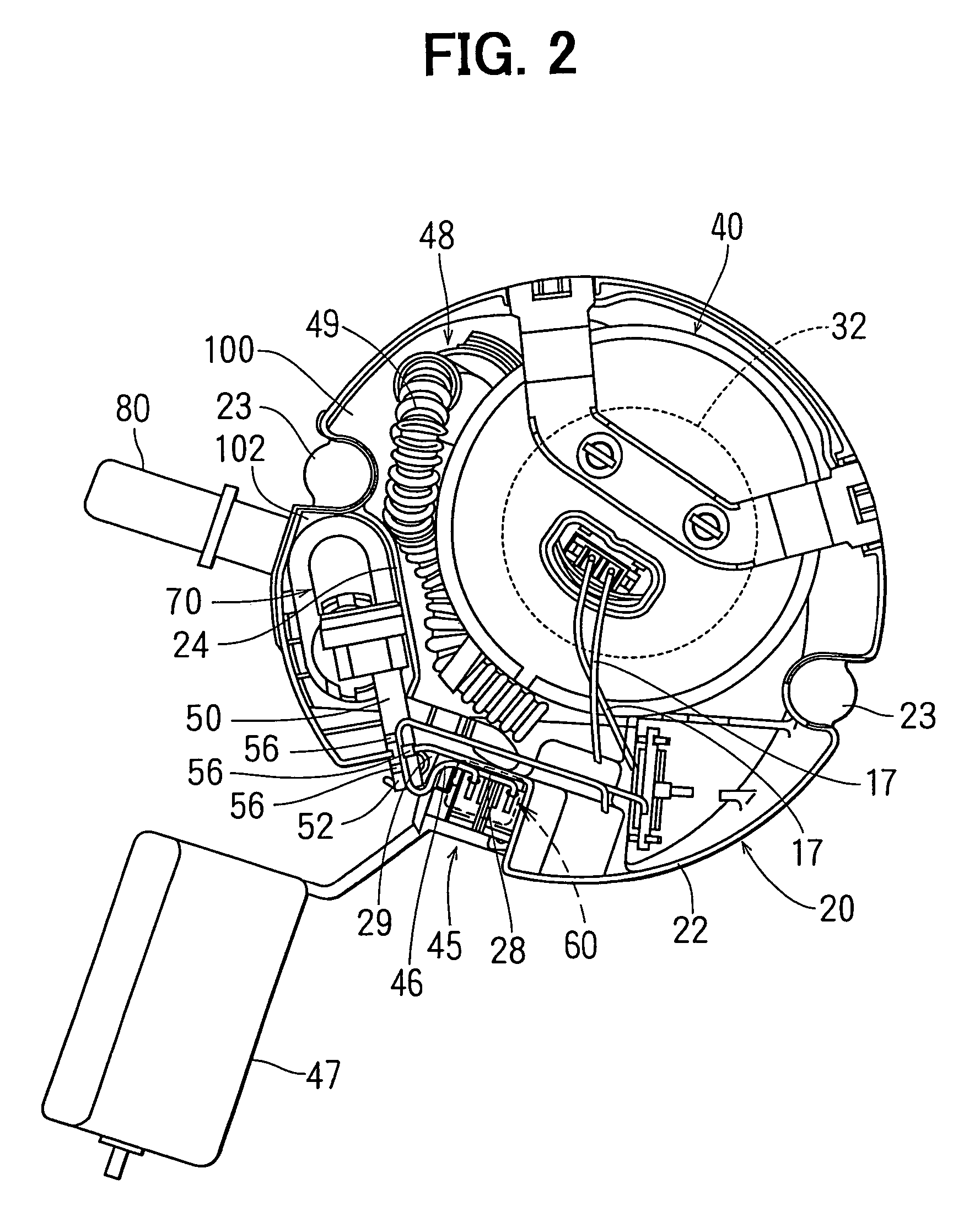
[0031]As shown in FIGS. 1 and 2, a fuel feed apparatus 1 is received in a fuel tank 2 for transferring fuel in the fuel tank 2 to an exterior device, such as engine, provided outside of the fuel tank 2. The fuel feed apparatus 1 includes a flange 10, a sub-tank 20, a pump module 40, a jet pump 60 (first jet pump), a jet pump 70 (second jet pump) and the like. FIG. 1 shows a cross-sectional view taken along a polygonal line passing the jet pump 60, a pressure regulator 48 and the jet pump 70 in FIG. 2. Here, the jet pump 60 is located under a sender gauge 45, and is not shown in FIG. 2. Therefore, the cross-sectional view shown in FIG. 1 is wider than a cross-sectional view taken along a straight line. The flange 10 is formed in a disc-shape and used as a lid in the fuel feed apparatus 1.
[0032]Referring back to FIG. 1, pump module 40 includes a filter case 41 and a filter element (fuel filter) 43. The filter case 41 surrounds the outer periphery of the fuel pump 32....
second embodiment
[Second Embodiment]
[0073]As shown in FIG. 6, fuel is pressurized in the fuel pump 32 and discharged from the vent hole 202 of the fuel pump 32. The vent hole 202 is connected with the jet pump 60 through a first pipe 326. The first pipe 326 is equivalent to the nylon pipe 50 in the first embodiment.
[0074]As shown in FIG. 7, the fuel pump 32 has a housing 350. The housing 350 receives a discharge-side cover 346, an armature 368, four magnets 370, a casing 366, suction-side cover 362 and the like. Each magnet 370 is shaped in an arc-shape in its cross-section. The four arc-shaped magnets 370 are arranged in the inside peripheral wall of the housing 350 in a predetermined interval, so that different magnetic poles are alternatively formed in the circumferential direction of the housing 350.
[0075]The armature 368 is rotatably received in the housing 350 with the shaft 37. A commutator 348 is provided on the one end of the armature 368. The shaft 37 is press-inserted into a core 352. Mul...
third embodiment
[Third Embodiment]
[0092]As shown in FIG. 9, fuel is drawn from the second pipe 312, and supplied into the jet pump 60 in this embodiment.
[0093]Specifically, a fourth pipe 376 is connected with the second pipe 312 for introducing fuel discharged from the discharge port 40a of the pump module 40 into the jet pump 60. Fuel is pressurized in the fuel pump 32 by rotation of the impeller 34, and flows into the second pipe 312 through the filter element 43. Fuel flowing in the second pipe 312 is partially introduced into the jet pump 60 through the fourth pipe 376. The fuel introduced into the jet pump 60 is jetted from the nozzle 62 into the sub-tank 20. The amount of fuel introduced into the jet pump 60 corresponds to the flow passage area of the nozzle 62 of the jet pump 60.
[0094]Fuel is introduced from the upstream side of the valve port 342 of the pressure regulator 48 into the jet pump 60. Accordingly, pressure in the downstream side of the pressure regulator 48 is not affected by th...
PUM
 Abstract
Description
Claims
Application Information
 - R&D
- Intellectual Property
- Life Sciences
- Materials
- Tech Scout
- Unparalleled Data Quality
- Higher Quality Content
- 60% Fewer Hallucinations
Browse by: Latest US Patents, China's latest patents, Technical Efficacy Thesaurus, Application Domain, Technology Topic, Popular Technical Reports.
© 2025 PatSnap. All rights reserved.Legal|Privacy policy|Modern Slavery Act Transparency Statement|Sitemap|About US| Contact US: help@patsnap.com


