Coaxial horn antenna system

a horn antenna and coaxial technology, applied in the direction of antennas, waveguide horns, electrical equipment, etc., can solve the problems of system not offering concurrent operation on spectrally offset frequency bands, system specifications that cannot be changed and system specifications that cannot be maintained without changing the design of main reflectors. , to achieve the effect of minimizing the interaction of corrugations

Inactive Publication Date: 2006-01-03
NORTH SOUTH HLDG
View PDF10 Cites 238 Cited by
  • Summary
  • Abstract
  • Description
  • Claims
  • Application Information

AI Technical Summary

Benefits of technology

[0011]The invention concerns an antenna feed system. The feed system can include a plurality of RF horn antennas for operating on a plurality of RF frequency bands. A first one of the feed horns can have a boresight axis and is configured for operating at a first one of the frequency bands. A second one of the feed horns is positioned coaxially within the first one of the feed horns and is configured for operating at least at a second one of the frequency bands. Further, the first one of the feed horns is a corrugated horn that has a plurality of corrugations formed on an interior surface defining a profile. The profile extends substantially from a throat of the first feed horn and along a tapered portion of the first feed horn. The profile substantially minimizes an interaction of the corrugations with the second feed horn.
[0013]Further, a slot depth of the corrugations can advantageously selected to improve the performance of the coaxial antenna feed system. For example, the slots can define a matching section in the throat portion of the horn. The slots in this matching section can have a depth that tapers exponentially from about ½ wavelength at the portion of the matching section nearest the waveguide feed, to about ¼ wavelength at the portion of the matching section that is nearest the aperture. A remainder of the slots can have a depth of less than ¼ wavelength at a lowest operating frequency of the first feed horn.

Problems solved by technology

In those situations where a single coaxial feed for multiple bands is desired, it can be challenging to maintain existing system specifications without changing the design of the main reflector and the sub-reflector.
Further, space limitations associated with existing designs can severely restrict design options.
Accordingly, that system does not offer concurrent operation on spectrally offset frequency bands.
Further, with conventional designs it can difficult to obtain the desired gain performance or illumination required to meet system specifications.
Still, in the case where multi-band operation of a ring focus reflector system is required, a single corrugated horn antenna has generally proved to be unsuitable.
Despite the availability of such techniques, it is not always possible to optimize a single corrugated horn antenna to produce a suitable illumination pattern at widely separated frequencies of interest.
Coaxial horns, such as those disclosed in U.S. Pat. No. 5,907,309 to Anderson et al. and U.S. Pat. No. 6,323,819 to Ergene can be used to create a common feed for widely separated frequencies of interest, but do not offer the benefits provided by corrugated horn antennas.

Method used


Image

  • Coaxial horn antenna system
  • Coaxial horn antenna system
  • Coaxial horn antenna system

Examples


Embodiment Construction

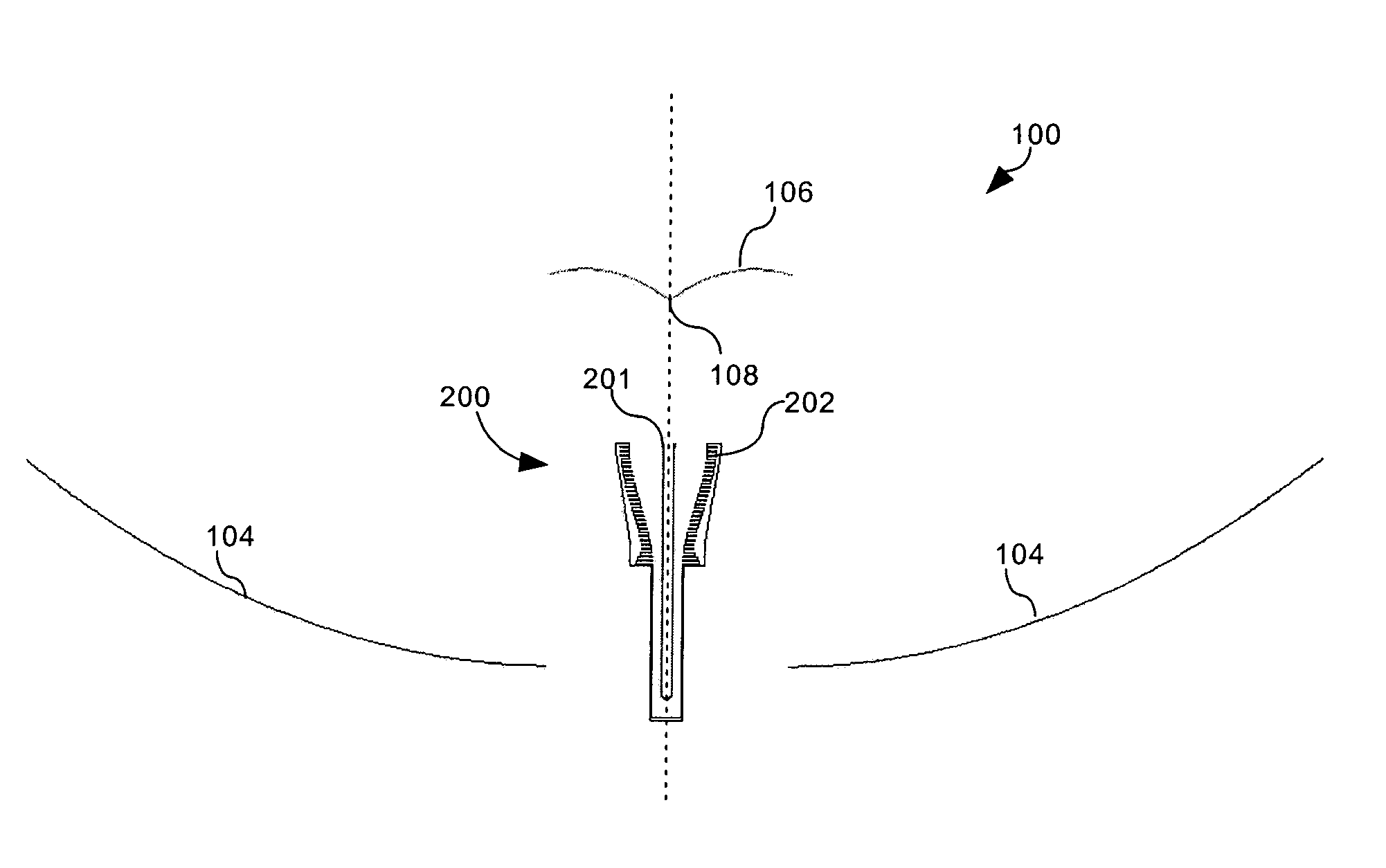
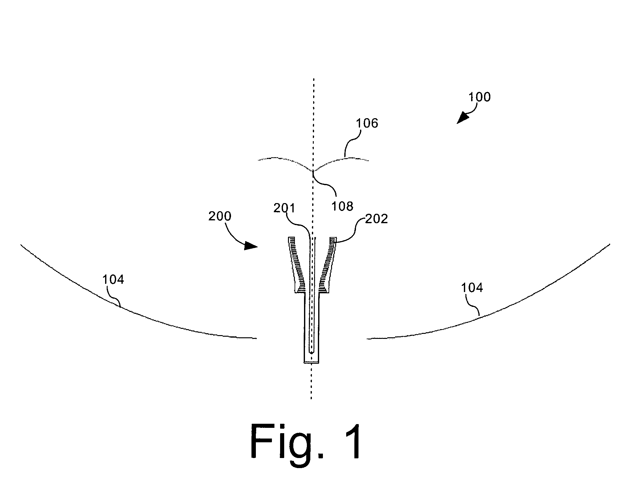
[0020]Referring to FIG. 1, a main reflector 104 and sub-reflector 106 are shown for a ring-focus, dual band antenna system 100. Ring-focus antenna systems are well known in the art. Such antennas are advantageous, as they are compact designs that offer acceptable performance for many communications applications. Main reflector 104 and sub-reflector 106 are typically shaped surfaces of revolution disposed about a boresight axis. Further, the main reflector 104 and the sub-reflector 106 can be designed for multi-band operation. For example, the main reflector and the sub-reflector can be designed to operate concurrently at X-band, K-band and Ka-band.

[0021]In a conventional ring-focus antenna systems, interchangeable microwave feed horn antennas can be swapped out for operating on different frequency bands. For example, one horn can be designed for operation on X-band whereas a second horn can be designed for operation on K-band. By swapping out different horns, the antenna system can ...


PUM


Abstract

An antenna feed system includes a plurality of RF horn antennas (201, 202) for operating on a plurality of RF frequency bands. A first one of the feed horns (202) can have a boresight axis and is configured for operating at a first one of the frequency bands. A second one of the feed horns (201) is positioned coaxially within the first one of the feed horns (202) and is configured for operating at least at a second one of the frequency bands. Further, the first one of the feed horns (202) is a corrugated horn that has a plurality of corrugations (204) formed on an interior surface defining a profile. The profile extends substantially from a throat (205) of the first feed horn and along a tapered portion of the first feed horn. The profile substantially minimizes an interaction of the corrugations with the second feed horn.

Description

RESEARCH OR DEVELOPMENT[0001]The United States Government has rights in this invention pursuant to Contract No. N00039-00-D-3210, between the United States Navy and Harris Corporation.BACKGROUND OF THE INVENTION[0002]1. Statement of the Technical Field[0003]The inventive arrangements relate generally to methods and apparatus for ring focus antennas and feed systems, and more particularly to ring focus antennas and feed systems that can operate in multiple frequency bands.[0004]2. Description of the Related Art[0005]It is often desirable for microwave satellite communication antennas to have the ability to operate on multiple frequency bands. In those situations where a single coaxial feed for multiple bands is desired, it can be challenging to maintain existing system specifications without changing the design of the main reflector and the sub-reflector. Further, space limitations associated with existing designs can severely restrict design options.[0006]U.S. Pat. No. 6,211,834 B1 ...

Claims


Application Information

Patent Timeline
Patent Type & Authority Patents(United States)
IPC IPC(8): H01Q13/00H01Q13/02H01Q19/19
CPCH01Q13/0208H01Q19/19H01Q13/0266
Inventor KRALOVEC, JAY A.GOTHARD, GRIFFIN K.DURHAM, TIMOTHY E.
Owner NORTH SOUTH HLDG
Why Eureka
Try Eureka