Signal processor

a technology of signal processor and signal processor, which is applied in the field of signal processor, can solve problems such as limiting the change rate, and achieve the effect of precise lock and large differences in occupancy

Inactive Publication Date: 2006-01-03
SONY UK LTD
View PDF10 Cites 27 Cited by
  • Summary
  • Abstract
  • Description
  • Claims
  • Application Information

AI Technical Summary

Benefits of technology

[0028]By monitoring the amount (reduction—carry) by which a change would exceed the limit and comparing it to the threshold, the encoding means can determine when VBV—lock is achieved or not. This allows lock to be achieved with large differences in occupancy between the bitstreams A and B. Preferably, if the limit is not exceeded, the limit is progressively reduced as the GOP proceeds. That prevents large changes at the end of the GOP. Preferably, if a change reduces occupancy, it is averaged (carry—over) over the remainder of the GOP to offset any increases which may occur later in the GOP. In an embodiment, if lock is not exactly achieved stuffing bits are added to the transitional GOP to achieve precise lock.

Problems solved by technology

Furthermore limiting the rate of change more evenly distributes the bits over the transitional region.

Method used


Image

  • Signal processor
  • Signal processor
  • Signal processor

Examples


first example

[0045]Referring to FIGS. 1, 3 and 7, two bitstreams A0 and B0 are MPEG-2 encoded with GOPs comprising 12 frames. In this example the bitstreams A0 and B0 have the same GOP structure:

IBBPBBPBBPBB

[0046]as shown in FIG. 7. However the bitstreams may have any other GOP structure allowed by MPEG-2. The two bitstreams A0 and B0 may have different GOP structures. For ease of explanation it is assumed the bitstreams A0 and B0 have the same GOP structure as shown in FIG. 7.

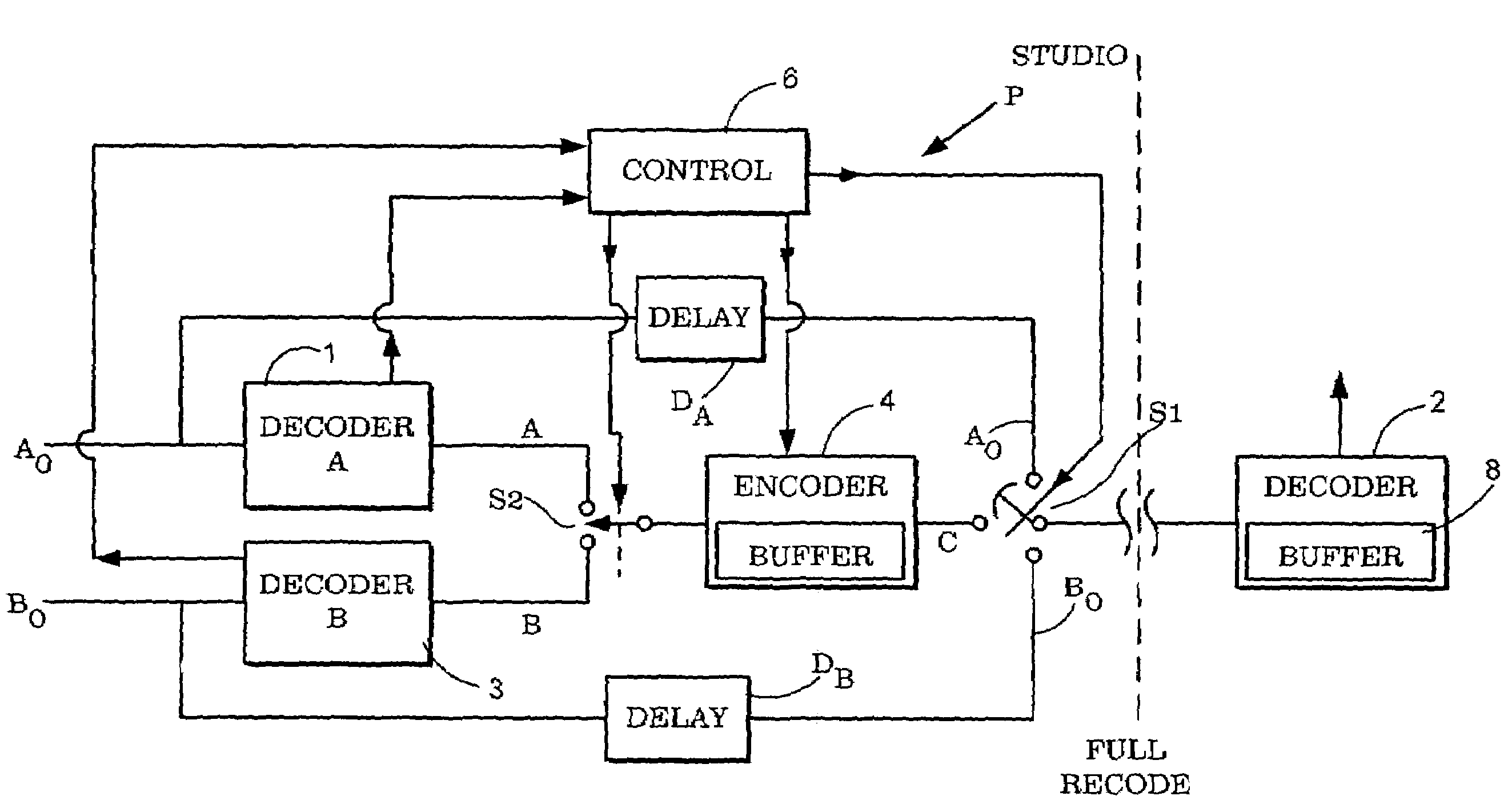
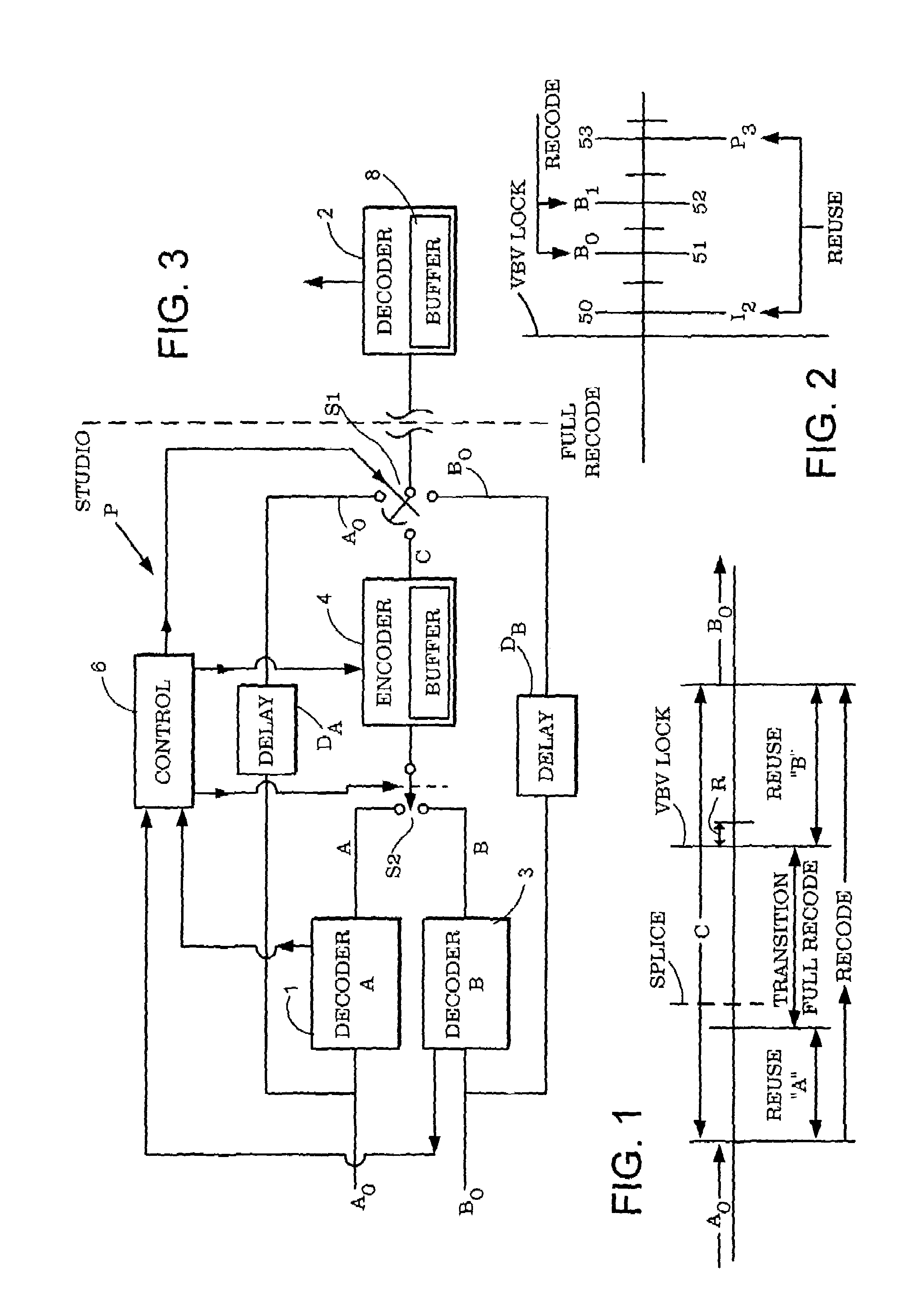
[0047]It is desired to replace bitstream A0 by bitstream B0. As shown in FIG. 1, initially A0 is provided to the processor. It is routed in the processor P of FIG. 3 from input A0 to contact A0 of switch Si where it is fed, unchanged to, for example, a downstream decoder 2. In decoder 2 it is decoded for display. Downstream decoder 2 may be in, for example, a domestic television receiver. Processor P may be in a studio.

[0048]When an operator decides to splice bitstreams B0 and A0, the operator operates the switch S1 and a ...

second example

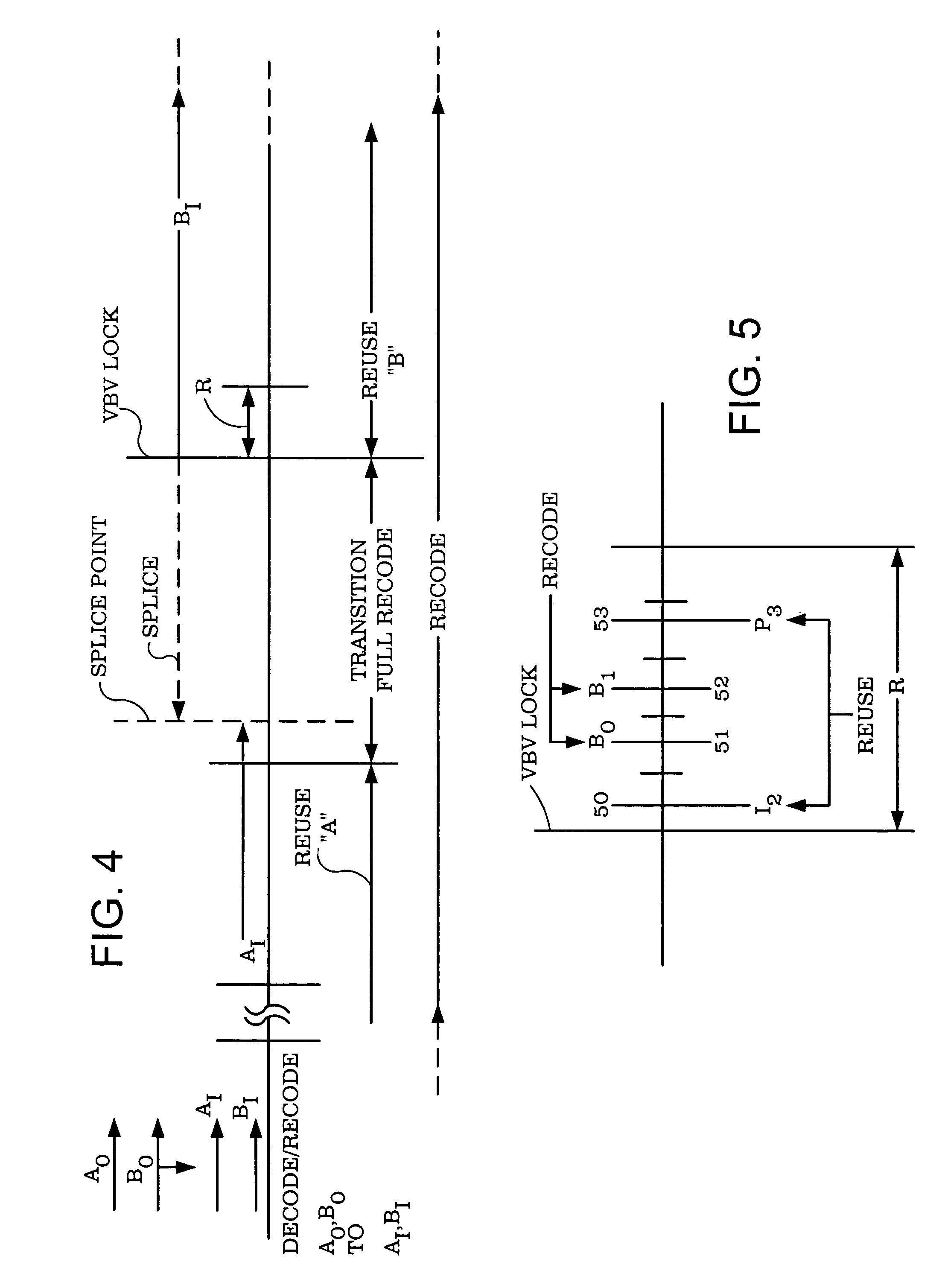
[0055]Referring to FIGS. 4, 6A and 7, two first generation (Gen1) bitstreams A0 and B0 are MPEG-2 encoded with GOPs comprising 12 frames. In this example the bitstreams A0 and B0 have the same GOP structure:


PUM

PropertyMeasurementUnit
thresholdaaaaaaaaaa
thresholdaaaaaaaaaa
reductionaaaaaaaaaa

Abstract

Decoders A and B decode MPEG-2 bitstreams A and B. A switch (S1) switches from decoded stream A to decoded stream B to achieve a splice. The resulting bitstream is re-encoded in an encoder 4. A new transitional GOP is defined beginning at the splice. The new GOP is defined by picture type decision rules which may have the effect of changing the GOP compared to the GOPs of streams A and B. The new GOP provides an initial prediction of the position in stream B where the occupancy value of stream C should coincide with that of B. A target for the new number of bits in the new GOP is calculated as the sum of the normal allocation of bits for the new GOP plus the difference between the occupancy value of stream C at the splice and a prediction of the occupancy of stream B at the predicted position. The occupancy value of stream C is controlled in accordance with the target so that it tends towards the occupancy value of stream B at the predicted position.
The target is updated regularly throughout the GOP on I and P frames. After the first update at the beginning of the transitional GOP, the target changes at the updates nominally by an amount VBVdiff which is the difference between occupancy of bit stream B on the current I or P frame and the occupancy at the next I or P frame. If VBV-diff is negative, the amount of change is limited to a limit value. The maximum value of the limit may be exceeded only once and the limit is then set to zero. The excess of VBVdiff over the limit is a value reductioncarry. Reduction carry is monitored, and if at the end of the transitional GOP it exceeds a threshold (e.g. zero), another transitional GOP is started. If VBVdiff is negative but does not exceed the limit, the target is reduced by VBVdiff and the limit is reduced by a proportion of VBVdiff. If VBVdiff is positive, then VBVdiff is averaged out over the target values for the remaining I and P frames in the GOP.

Description

BACKGROUND OF THE INVENTION[0001]1. Field of the Invention[0002]The present invention relates to a signal processor. The invention concerns, joining referred to herein as splicing, digital bit streams which are compressed. Embodiments of the invention described herein are concerned with splicing digital video bitstreams which are compressed according to the MPEG-2 standard.[0003]2. Description of the Prior Art[0004]The invention and its background will be discussed by way of example with reference to MPEG-2 video bitstreams. However the invention is not limited to MPEG-2.[0005]MPEG-2 is well known from for example ISO / IEC / 13818-2, and will not be described in detail herein. Splicing of video is well known. It is used in editing video. Splicing analogue signals is relatively straight forward and can be done at the boundary between adjacent frames, because each analogue frame contains the whole of the video information of that frame independently of other frames. (Splicing can be done...

Claims


Application Information

Patent Timeline
Patent Type & Authority Patents(United States)
IPC IPC(8): H04N7/12G11B27/032G11B27/036H03M7/30H04N7/24H04N7/26H04N7/50
CPCH04N19/40H04N21/23424H04N21/44016H04N19/159H04N19/172H04N19/149H04N19/15H04N19/115H04N19/61H04N19/114H04N19/124H04N19/152H04N19/177G11B27/036G11B27/032G11B2220/90
Inventor SAUNDERS, NICHOLAS IANPORTER, ROBERT MARK STEFAN
Owner SONY UK LTD
Why Eureka
Try Eureka