
Heat transport device, semiconductor apparatus using the heat transport device and extra-atmospheric mobile unit using the heat transport device

a heat transport device and heat transport technology, applied in the direction of insulated conductors, semiconductor/solid-state device details, cables, etc., can solve the problems of increasing the amount of heat radiated from the equipment, reducing the efficiency of reducing the noise of equipment, etc., to achieve high heat transportation and heat radiating capacity, improve temperature controllability, and reduce nois

Inactive Publication Date: 2006-01-10
MITSUBISHI ELECTRIC CORP
View PDF19 Cites 24 Cited by
  • Summary
  • Abstract
  • Description
  • Claims
  • Application Information

AI Technical Summary

Benefits of technology

[0011]The present invention is intended to overcome the aforementioned problems of the prior art. Accordingly, it is an object of the invention to provide a heat transport device featuring low acoustic noise performance and improved temperature controllability as well as high heat transportation and heat radiating capacities. It is another object of the invention to provide a heat transport device capable of offering improved performance as a bubble lift pump. It is a further object of the invention to provide a heat transport device using a working fluid having improved heat transfer and flow characteristics.
[0012]According to the invention, a heat transport device includes a container having a hollow structure in which a fluid channel is formed, at least one each thermal-receiver-type heat exchanger and thermal-radiator-type heat exchanger arranged on an outer wall of the container along the fluid channel, and driving heat exchangers provided at both terminal portions of the container. In this heat transport device, both ends of the fluid channel are closed to prevent intrusion of external air, and a liquid and gas are sealed in the fluid channel. The driving heat exchangers cause the liquid to oscillate in the container along its fluid channel.
[0013]Since the driving heat exchangers provided at both terminal portions of the container cause the liquid to oscillate along the fluid channel, the heat transport device offers low acoustic noise performance and improved temperature controllability as well as an enhanced heat transport efficiency.

Problems solved by technology

It has however become difficult in recent years to cool electronic and other types of equipment by using heat pipes as a result of a rapid increase in the amount of heat radiated from the equipment.
In addition, as it is fairly difficult to control the temperature with a heat pipe, there has been a pending need for a heat transport device which allows easy temperature control.
In this heat transport device, a power source supplies a voltage of a pulse-shaped waveform to the heating unit to heat the liquid inside the capillary tube in a steplike fashion, eventually causing the liquid to bump.
The aforementioned conventional heat transport device has a problem that its heat transportation and heat radiating capacities are low.
Although the liquid used as a working fluid should preferably have properties suited to a bubble lift pump as well as good heat transfer and flow characteristics, it has so far been extremely difficult to satisfy all these requirements.
In other words, there has been a problem that it is difficult to increase the amplitude of oscillation and reduce the period of oscillation of the working fluid for improving the performance of the bubble lift pump and to improve the heat transfer and flow characteristics of the working fluid.

Method used


Image

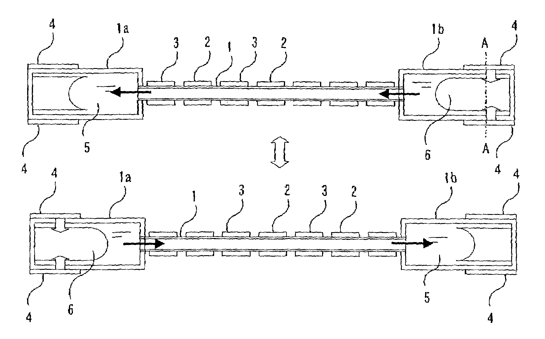
  • Heat transport device, semiconductor apparatus using the heat transport device and extra-atmospheric mobile unit using the heat transport device
  • Heat transport device, semiconductor apparatus using the heat transport device and extra-atmospheric mobile unit using the heat transport device
  • Heat transport device, semiconductor apparatus using the heat transport device and extra-atmospheric mobile unit using the heat transport device

Examples


first embodiment

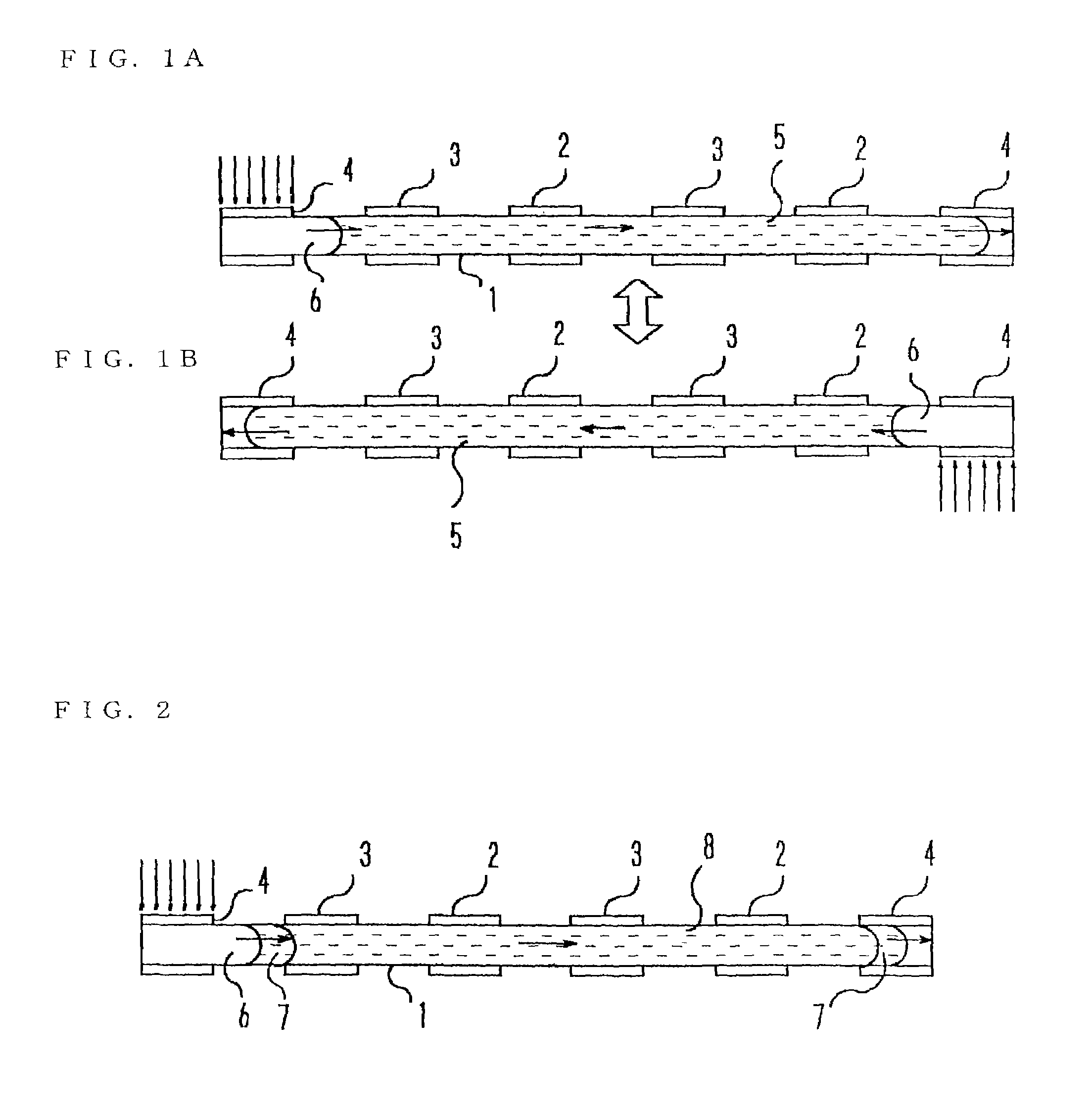
[0049]FIGS. 1A–1B are sectional diagrams showing the construction of a heat transport device according to a first embodiment of the invention, in which the numeral 1 designates a container. The container 1 is not particularly limited in its physical size. It may be formed of a microtube, for example, in which case, the invention can be applied to a microstructure such as a semiconductor apparatus.

[0050]As shown in FIGS. 1A–1B, appropriate quantities of a liquid 5 and a gas 6 are sealed in the container 1 and one each or more thermal-receiver-type heat exchangers 2 and thermal-radiator-type heat exchangers 3 are alternately arranged side by side on an outer wall of the container 1 along its length, with driving heat exchangers 4 provided at both terminal portions of the container 1.

[0051]The interior of the container 1 forms a fluid channel in which the liquid 5 and the gas 6 move. The thermal-receiver-type heat exchangers 2 are heat generating portions of an electronic apparatus or ...

second embodiment

[0058]In the heat transport device of FIGS. 1A–1B, it is preferable that the internal volume V1 of a portion of the container 1 where each driving heat exchanger 4 is provided be equal to or larger than the internal volume V2 of that portion of the container 1 which is bounded by the center of each thermal-receiver-type heat exchanger 2 and the center of its adjacent thermal-radiator-type heat exchanger 3. It is also preferable that the total volume V3 of the liquid 5 be approximately equal to a value obtained by subtracting the volume V1 from the total internal volume V of the container 1.

[0059]If the heat transport device is designed such that the internal volumes V1, V2 and the volume V3 satisfy the relationships V1≧V2 and V3≈V−V1, the liquid 5 can be caused to oscillate with a large amplitude. When a larger oscillation of the liquid 5 is produced in this fashion, masses of the liquid 5 move between multiple pairs of the thermal-receiver-type heat exchangers 2 and the thermal-rad...

third embodiment

[0060]FIG. 2 is a sectional diagram showing the construction of a heat transport device according to a third embodiment of the invention, in which elements identical or similar to those depicted in FIGS. 1A–1B are designated by the same reference numerals. What is characteristic of the third embodiment is that it employs a combination of a low-boiling liquid 7 and a high-boiling liquid 8 which do not mix and remain separated from each other.

[0061]The low-boiling liquid 7 should be a liquid which shows a large volumetric change with a small amount of heat input. For example, a liquid having a small amount of latent heat and a large difference in density between the liquid and vapor phases is sealed in both terminal portions of a container 1 where the liquid is held in contact with driving heat exchangers 4. On the other hand, the high-boiling liquid 8 should be a liquid which has a higher boiling point than the low-boiling liquid 7, high fluidity and good heat transportation performa...


PUM


Abstract

A heat transport device includes a container having a hollow structure including a fluid channel, at least one thermal-receiver heat exchanger and one thermal-radiator heat exchanger arranged side-by-side on an outer wall of the container along the fluid channel, and driving heat exchangers at respective terminal portions of the container. In this heat transport device, both ends of the fluid channel are closed to prevent intrusion of external air, and a liquid and a gas are sealed in the fluid channel. The driving heat exchangers cause the liquid to oscillate in the container along the internal fluid channel. The heat transport device provides low acoustic noise performance, improved temperature controllability, high heat transportation and heat radiating capacities, and improved heat transfer and fluid flow characteristics.

Description

CROSS-REFERENCES TO RELATED APPLICATIONS[0001]This application is a continuation-in-part of U.S. patent application Ser. No. 10 / 400,190 filed Mar. 27, 2003, now abandoned.BACKGROUND OF THE INVENTION[0002]1. Field of the Invention[0003]The present invention relates to a heat transport device used for cooling electronics equipment, for example.[0004]2. Description of the Background Art[0005]To meet requirements for reliability, lightweight design, and low acoustic noise performance, a heat pipe having no moving parts, unlike pumps, has conventionally been used as a heat transport device for cooling electronics equipment, for example. It has however become difficult in recent years to cool electronic and other types of equipment by using heat pipes as a result of a rapid increase in the amount of heat radiated from the equipment.[0006]In addition, as it is fairly difficult to control the temperature with a heat pipe, there has been a pending need for a heat transport device which allow...

Claims


Application Information

Patent Timeline
Patent Type & Authority Patents(United States)
IPC IPC(8): F28D15/00H05K7/20
CPCF28D15/0233F28D15/0266F28F3/12H01L23/427H05K7/20272F28D1/0383H01L2924/0002H01L2924/00
Inventor IPPOUSHI, SHIGETOSHIOGUSHI, TETSURONAKAO, KAZUSHIGEISHIKAWA, HIROAKIUMEMOTO, TOSHIYUKICHIBA, HIROSHISHIMOJI, MIHOKO
Owner MITSUBISHI ELECTRIC CORP
Learn More