Apparatus for controlling permanent-magnet rotary machine

a controller technology, applied in the direction of motor/generator/converter stopper, electronic commutator, dynamo-electric converter control, etc., can solve the problem that the disclosed technique cannot be applied to a salient-pole machine having a rotor, and the position of the magnetic pole that is detected by the magnetic pole position detector suffers an error. , to achieve the effect of efficiently controlling the operation of the permanent magnet rotary machin

Active Publication Date: 2006-01-10
HONDA MOTOR CO LTD
View PDF18 Cites 26 Cited by
  • Summary
  • Abstract
  • Description
  • Claims
  • Application Information

AI Technical Summary

Benefits of technology

[0014]It is therefore an object of the present invention to provide a control apparatus for controlling operation of a permanent-magnet rotary machine efficiently by properly correcting the detect

Problems solved by technology

While a permanent-magnet rotary machine with a magnetic pole position detector is being controlled, the positions of the magnetic poles that are detected by the magnetic pole position detector often suffer an error with respect to the actual positions of the magnetic poles due to an error caused in the positioning of the magnetic pole position detector when it is assembled and a limitation on the accuracy with which the magnetic pole position detector is manufactured.
However, the disclosed technique cannot be applied to a salient-pole machine having a rotor whose magnetic poles are salient poles because the torque T generated by the rotary machine is proportional to the q-axis current Iq.
Consequently, the above-mentioned basis of the technique disclosed in the above publication is not valid for salient-pole

Method used


Image

  • Apparatus for controlling permanent-magnet rotary machine
  • Apparatus for controlling permanent-magnet rotary machine
  • Apparatus for controlling permanent-magnet rotary machine

Examples


second embodiment

[0072] the process performed by the phase corrector 18 to determine the magnetic pole correcting angle θofs is shown in FIG. 6. The decision processing in STEP11 through STEP14 to determine whether conditions for determining the magnetic pole correcting angle θofs are satisfied or not is identical to the decision processing in STEP1 through STEP4 shown in FIG. 5. If the conditions in STEP11 through STEP14 are satisfied, then the phase corrector 18 performs the processing in STEPS 15 through 21 to determine the magnetic pole correcting angle θofs. In the process of determining the magnetic pole correcting angle θofs according to the present embodiment, the temporary setting correcting angle α is set to a plurality of values, and the magnetic pole correcting angle θofs is determined in a searching fashion. Specifically, in STEP15, the phase corrector 18 gives the current command switcher 10 a switching command for enabling the current command switcher 10 to output the d-axis current c...

first embodiment

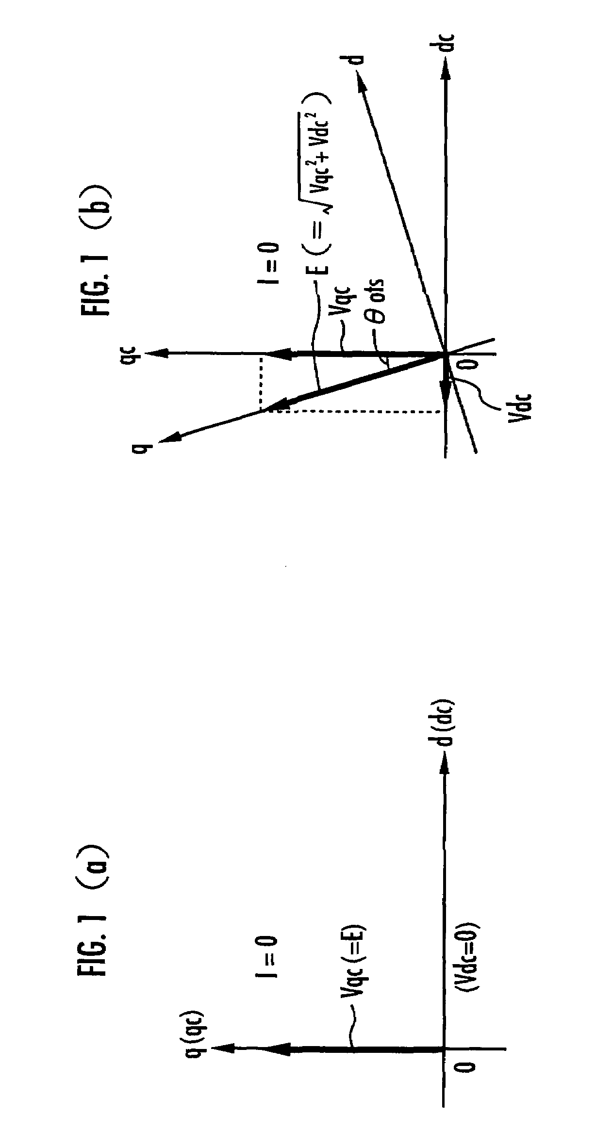
[0077]The magnetic pole correcting angle θofs thus obtained in STEP19 represents an error angle of the detected rotational angle θact with respect to the actual rotational angle of the magnetic poles according to the principles described above with reference to FIGS. 1(a) and 1(b). As with the first embodiment, since the magnetic pole correcting angle θofs is determined while the rotational speed ω of the motor 1 is equal to or smaller than a predetermined value and is substantially constant, the magnetic pole correcting angle θofs is obtained accurately. This holds true not only if the permanent magnet 5 of the rotor 4 is cylindrical, but also if it has salient poles.

[0078]According to the present embodiment, therefore, as with the first embodiment, the magnetic pole correcting angle θofs can be determined accurately with a simple arrangement irrespective of whether the motor 1 is a cylindrical machine or a salient-pole machine. Since the magnetic pole correcting angle θofs can be ...


PUM


Abstract

While a rotor 4 of a permanent-magnet rotary machine 1 is rotating and an armature current thereof is substantially zero, a motor controller 2 performs a dq vector control process to control the permanent-magnet rotary machine 1 in a dq coordinate system which has a d-axis representing the direction of a magnetic field of the rotor 4 and a q-axis representing a direction perpendicular to the d-axis, and determines a magnetic pole position correcting quantity θofs to correct a magnetic pole position θact detected by a magnetic pole position detector 8 so that a d-axis voltage command value Vdc determined by the dq vector control process will be substantially zero. The motor controller 2 controls the phases of armature voltages Vuc, Vvc, Vwc with magnetic pole positions corrected by the magnetic pole position correcting quantity θofs. Irrespective of whether the rotary machine 1 is a cylindrical machine or a salient-pole machine, the detected values of magnetic pole positions are appropriately corrected according to a simple process without the need for a voltage detector for thereby efficiently controlling operation of the permanent-magnet rotary machine 1.

Description

BACKGROUND OF THE INVENTION[0001]1. Field of the Invention[0002]The present invention relates to an apparatus for controlling a permanent-magnet rotary machine be, and more particularly to an apparatus for controlling an electric motor or generator having a permanent-magnet rotor.[0003]2. Description of the Related Art[0004]Permanent-magnet rotary machines, e.g., 3-phase DC brushless motors, having a permanent magnet and an armature respectively in a rotor and a stator are required to control the phase of a voltage applied to the armature (more specifically a voltage applied to the winding of each phase of the armature, hereinafter referred to as “armature-applied voltage”) depending on the positions of the magnetic poles of the rotor (more specifically the angular positions of the magnetic poles) in order to control the generated torque and the rotational speed thereof. The permanent-magnet rotary machines have a magnetic pole position detector for detecting the positions of the ma...

Claims


Application Information

Patent Timeline
IPC IPC(8): H02P1/46B60L50/16B60L15/02H02P1/18H02P3/08H02P6/06H02P6/08H02P6/17H02P6/18H02P6/182H02P6/28H02P21/00H02P21/06H02P21/10H02P21/22H02P21/36H02P25/026H02P27/04
CPCB60K6/26B60K6/48B60L15/025H02P6/182H02P21/0053H02P21/06H02P21/0042Y02T10/6221Y02T10/643H02P21/26H02P21/32Y02T10/62Y02T10/64
Inventor TAJIMA, SHIGERUINOUE, HIDEKI
Owner HONDA MOTOR CO LTD
Why Eureka
Try Eureka