Antenna

Inactive Publication Date: 2006-01-10
PANASONIC CORP
View PDF5 Cites 13 Cited by
  • Summary
  • Abstract
  • Description
  • Claims
  • Application Information

AI Technical Summary

Benefits of technology

[0012]To achieve the object above, the antenna of the invention is formed of i) a rod-like core made of insulating resin, and ii) an antenna element containing a feeding terminal secured to the core. Such structured antenna is mounted on a wireless device in such a way that the core is fitted in a notch formed in a wiring board of the wireless device and then the feeding terminal is soldered onto the wiring board of the device. Fitting the core into the notch of the wiring board allows the antenna to be properly positioned with respect to the wiring board. Besides, the feeding terminal can be soldered, as well as other components, in the same step. This contributes to decreased manufacturing cost. Furthermore, such mounted antenna can maintain secure connections with the wiring board of the wireless device, thereby ensuring electrical connections with reliability and mechanical strength against impact load from the outside.
[0013]It is another aspect of the present invention that i) the core is generally shaped into a rectangular parallelepiped, and ii) a joint section for soldering is disposed on side surfaces of the core other than the side surface on which the feeding terminal of the antenna element is provided. The core can be easily manufactured because of its simple shape. In addition, the antenna is soldered, through two or more positions on the side surfaces of the core, to the wiring board. This can provide a further steady mounting, which is resistant to impact load from the outside.
[0014]It is still another aspect of the present invention that the feeding terminal and the joint section are located substantially at the midpoint of a side surface of the core in the height direction. That is, the antenna is soldered to the wiring board of a wireless device so that the thickness of the core i

Problems solved by technology

This contributes to decr

Method used


Image

  • Antenna
  • Antenna
  • Antenna

Examples


Example

[0029]An embodiment of the present invention is described hereinafter with reference to the accompanying drawings, FIG. 1 through FIG. 8.

Exemplary Embodiment

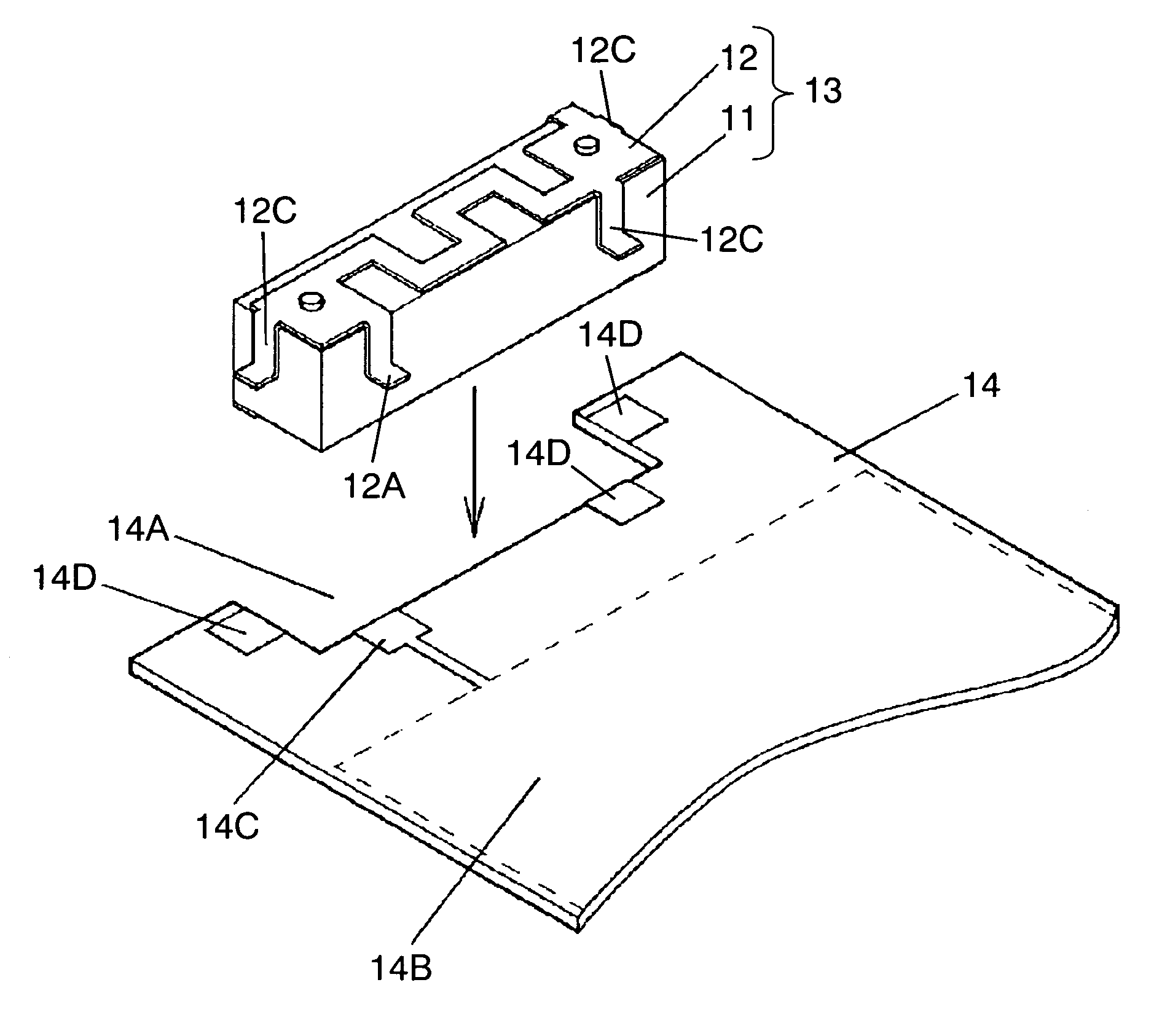
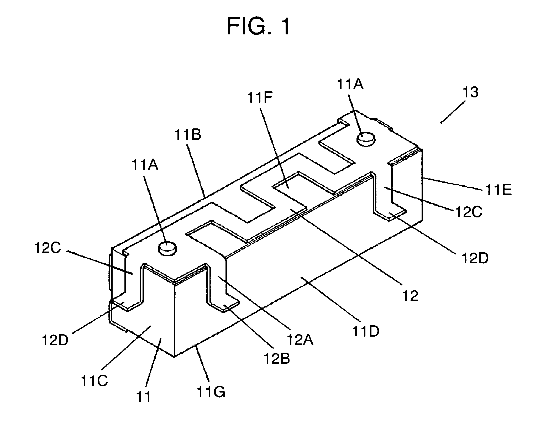
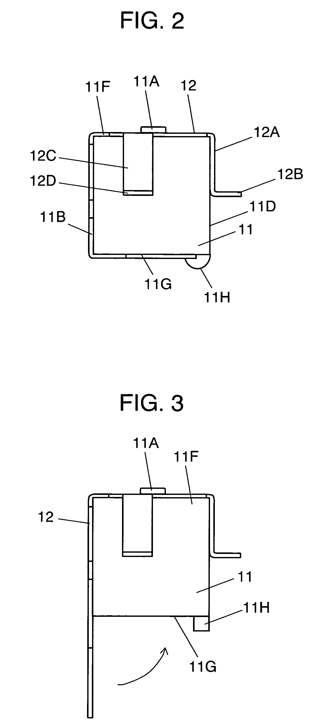
[0030]FIG. 1 is a perspective view showing the appearance of an antenna in accordance with an embodiment of the present invention, and FIG. 2 is a side view of the antenna shown in FIG. 1. Insulating resin-made core 11, which is generally formed into a rectangular parallelepiped, contains two caulking projections 11A on upper surface 11F.

[0031]Antenna element 12, which is a metallic thin plate, is formed into U shape in section through blanking and bending processes.

[0032]Antenna element 12 is disposed on core 11 in such a way that the U shape conforms to top surface 11F, side surface 11B, and bottom surface 11G, and then secured to core 11 by caulking at caulking projections 11A on top surface 11F and a caulking projection (not shown) disposed at the edge of bottom surface 11G.

[0033]Antenna element 12 contains an element sectio...


PUM


Abstract

An antenna providing easy and effective mounting procedures onto a wireless device for mobile communications and highly reliable electrical connections. The antenna contains insulating resin-made core 11 that is generally formed into a rectangular parallelepiped, and metallic thin-plate antenna element 12 from which feeding terminal 12A and joint sections 12C are extended. Antenna element 12 is disposed on top surface 11F, side surface 11B, and bottom surface 11G of core 11. Antenna element 12 is then fixed to core 11 by caulking at caulking projections 11A formed on the top surface of core 11. Feeding terminal 12A is bent to have L-shaped tip 12B on side surface 11D; similarly, joint sections 12C are bent to have L-shaped tips 12D on side surfaces 11C and 11E. These tips are bent at the same level according to the thickness of a wiring board to be soldered.

Description

FIELD OF THE INVENTION[0001]The present invention relates to an antenna used for a wireless device for mobile communications such as a handy telephone.BACKGROUND ART[0002]Recently, wireless devices for mobile communications including a handy telephone have been getting smaller and more multi-functional. Accordingly, as an antenna to be mounted on such a compact device, a built-in type has become popular.[0003]Here will be described a conventional built-in type antenna with reference to FIG. 10 and FIG. 11. FIG. 10 is a perspective view showing the appearance of a conventional antenna. Insulating resin-made core 1 has body 1A generally shaped into a rectangular parallelepiped. Three projections 1C, which project from each periphery of three corners of body 1A, are disposed in parallel with each other. Each of projections 1C has hole 1B therein.[0004]Antenna element 2, which is made of a metallic thin plate, is calked on the upper side of core 1 with projections 1D disposed on the upp...

Claims


Application Information

Patent Timeline
IPC IPC(8): H01Q1/24H01Q1/12H01Q1/38H01Q9/30
CPCH01Q1/1207H01Q1/38H01Q1/243
Inventor SADAMORI, HIDETONAKAGAWA, YOSHINOBU
Owner PANASONIC CORP
Why Eureka
Try Eureka