Multi-band horn antenna using frequency selective surfaces

a frequency selective surface and antenna technology, applied in the field of horn antennas, can solve the problems of limiting the operational bandwidth of a waveguide, affecting the operation of conventional waveguides, and other modes with different field configurations can occur unintentionally or deliberately, so as to increase the permeability and/or the permittivity of the substrate, reduce the grating lobe of the antenna, and increase the permeability

Inactive Publication Date: 2006-01-10
NORTH SOUTH HLDG
View PDF28 Cites 233 Cited by
  • Summary
  • Abstract
  • Description
  • Claims
  • Application Information

AI Technical Summary

Benefits of technology

[0015]The present invention also relates to a waveguide horn antenna which includes a tapered hollow metallic conductor, a FSS including a substrate, and an array of elements defining at least one wall of the horn. The waveguide can be filled with a material having a permeability and a permittivity of about 1. The FSS can include concentric ring slots and is positioned for confining and guiding a propagating electromagnetic wave. A grating lobe of the antenna is reduced by increasing a permeability and / or a permittivity of the substrate to a value greater than about three. Further, at least one grating lobe of the antenna can be reduced by decreasing a spacing between adjacent elements of the FSS.
[0016]The value of the permeability and / or the permittivity can be selected to improve broadband performance of the FSS. For example, the permeability and / or the permittivity can be selected so that the FSS has a percentage bandwidth of at least 45%. The value of the permeability and / or the permittivity can be between about 10 and 100. Further, the permeability and / or the permittivity can be selected for improved performance of RF signals having an angle of incidence ranging from about 20 to 40 degrees relative to a plane which is perpendicular to the FSS.

Problems solved by technology

At higher frequencies, higher modes are supported and will tend to limit the operational bandwidth of a waveguide.
Other modes with different field configurations can occur unintentionally or can be caused deliberately.
Since waveguides are generally designed to have a static geometry, the operational frequency and bandwidth of conventional waveguides is limited.
This concept is not without its drawbacks, however.

Method used


Image

  • Multi-band horn antenna using frequency selective surfaces
  • Multi-band horn antenna using frequency selective surfaces
  • Multi-band horn antenna using frequency selective surfaces

Examples


Embodiment Construction

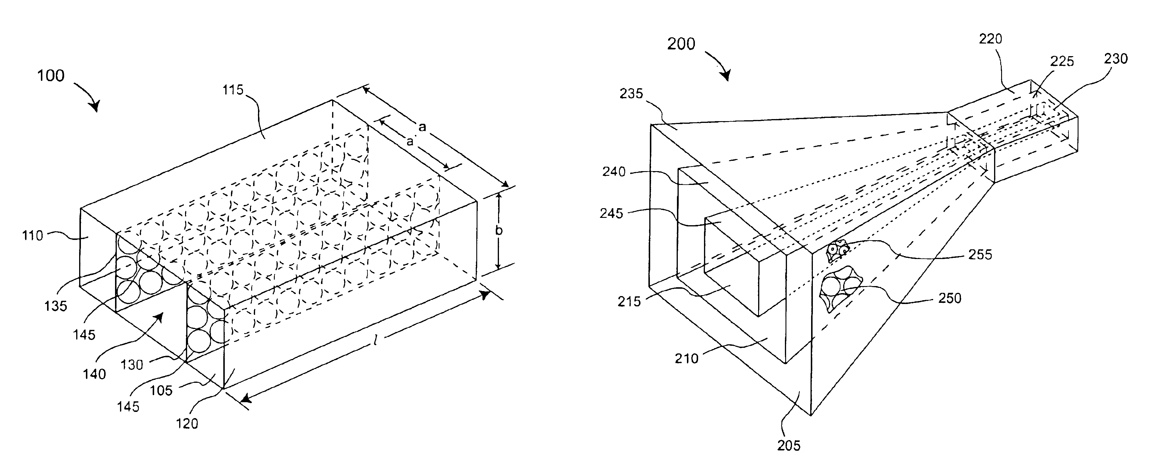
[0031]The present invention concerns a waveguide including a frequency selective surface (FSS), which comprises FSS elements having relatively small inter-element spacing for a given operational frequency. As compared to conventional FSS's, the small inter-element spacing increases FSS bandwidth and eliminates grating lobes by displacing them to higher frequencies. Further, FSS performance with respect to signal angle of incidence is improved.

[0032]Referring to FIG. 1, an exemplary multi-band waveguide (waveguide) 100 including FSS's 130, 135 is shown. The exemplary waveguide 100 has a rectangular cross section, however, the present invention is not so limited. Importantly, the present invention can be a waveguide having any suitable configuration defining a waveguide cavity 140. For example, the waveguide can have a cross section which is round, square, elliptical, triangular, or any other suitable shape. Further, the waveguide cavity 140 can be filled with a dielectric material or...


PUM


Abstract

A waveguide (100) including at least one outer surface (105, 110, 115, 120) defining a waveguide cavity (140) and at least one inner surface (130, 135) positioned within the waveguide cavity (140). The inner surface (130, 135) includes a frequency selective surface (FSS) having a plurality of FSS elements (145) coupled to at least one substrate. The substrate defines a first propagation medium such that an RF signal having a first wavelength in the first propagation medium can pass through the FSS (130, 135). The FSS (130, 135) is coupled to a second propagation medium such that in the second propagation medium the RF signal has a second wavelength which is at least twice as long as a physical distance between centers of adjacent FSS elements (145). The second wavelength can be different than the first wavelength.

Description

BACKGROUND OF THE INVENTION[0001]1. Statement of the Technical Field[0002]The inventive arrangements relate generally to methods and apparatus for horn antennas, and more particularly to horn antennas which can operate in multiple frequency bands.[0003]2. Description of the Related Art[0004]Conventional electromagnetic waveguides and horn antennas are well known in the art. A waveguide is a transmission line structure that is commonly used for microwave signals. A waveguide typically includes a material medium that confines and guides a propagating electromagnetic wave. In the microwave regime, a waveguide normally consists of a hollow metallic conductor, usually rectangular, elliptical, or circular in cross section. This type of waveguide may, under certain conditions, contain a solid, liquid, liquid crystal or gaseous dielectric material.[0005]In a waveguide, a “mode” is one of the various possible patterns of propagating or standing electromagnetic fields. Each mode is characteri...

Claims


Application Information

Patent Timeline
Patent Type & Authority Patents(United States)
IPC IPC(8): H01Q19/00H01P1/207H01Q5/00H01Q5/47H01Q13/02H01Q15/00H01Q25/04
CPCH01Q13/02H01Q5/47H01Q15/0013H01Q13/0283
Inventor ZARRO, MICHAEL S.DELGADO, HERIBERTO J.KILLEN, WILLIAM D.
Owner NORTH SOUTH HLDG
Why Eureka
Try Eureka