Non-inverting transflective assembly

a transflective assembly, non-inverting technology, applied in the direction of optics, polarising elements, instruments, etc., can solve problems such as substantial light loss

Inactive Publication Date: 2006-01-10
3M INNOVATIVE PROPERTIES CO
View PDF85 Cites 198 Cited by
  • Summary
  • Abstract
  • Description
  • Claims
  • Application Information

AI Technical Summary

Problems solved by technology

This, however, results in substantial loss of light because the backlight generally emits unpolarized light.

Method used


Image

  • Non-inverting transflective assembly
  • Non-inverting transflective assembly
  • Non-inverting transflective assembly

Examples


Embodiment Construction

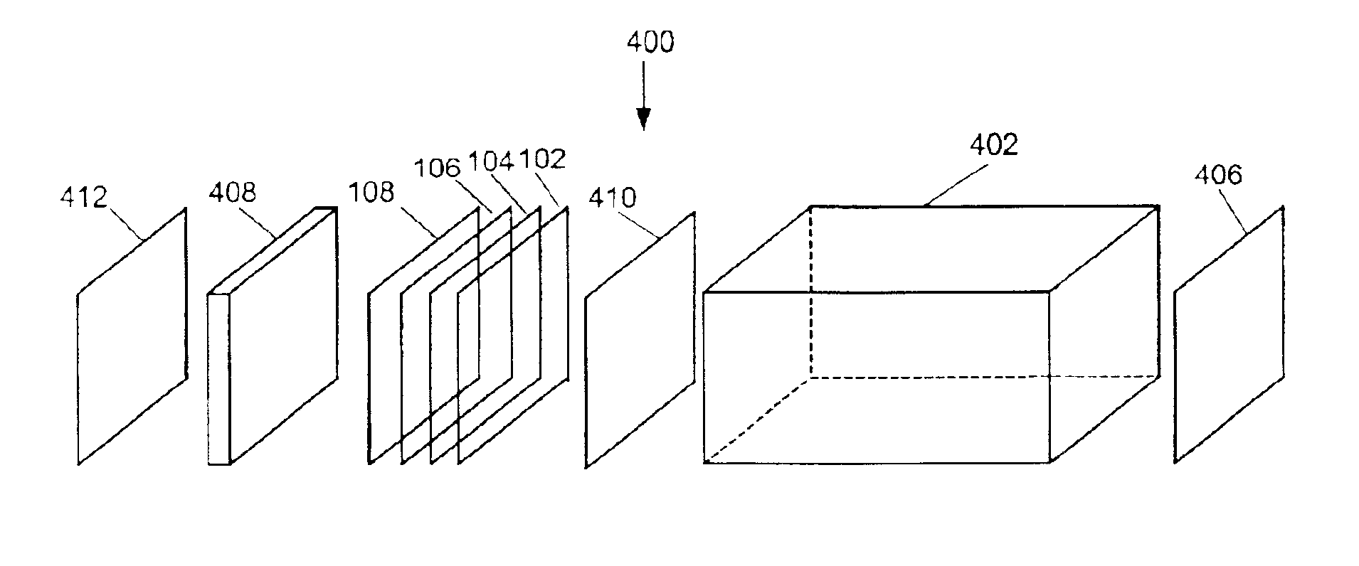
[0026]The present invention is directed to a method of embodying a non-inverting transflector in a roll-to-roll lamination process. Articles of the present invention generally include reflective polarizers between which is located a polarization rotator, a depolarizing layer, or both. The polarization rotator can be, for example, a polarizer, a compensation film, a Brewster-type polarizing device, or a polarizing lightguide. One embodiment of the invention involves linear reflecting polarizer films with parallel polarization axes, between which is located a polarization rotator, a depolarizing layer, or both.

[0027]The transflective displays described can also use the advantageous properties of multilayer optical films as reflective polarizers. The advantages, characteristics and manufacturing of such films are described, for example, in U.S. Pat. Nos. 5,882,774 and 5,965,247, both of which are herein incorporated by reference. The multilayer optical film is useful, for example, as m...


PUM

PropertyMeasurementUnit
twist angleaaaaaaaaaa
thicknessaaaaaaaaaa
thicknessaaaaaaaaaa

Abstract

A film that includes a first reflective polarizer substantially reflecting light having a first polarization state and substantially transmitting light having a second polarization state, a polarization rotating layer or depolarizing layer (or both) positioned to receive light passing through the first reflective polarizer, and a second reflective polarizer positioned to receive light passing through the polarization rotating layer or depolarizing layer, the second reflective polarizer substantially reflecting light having a third polarization state back through the polarization rotating layer or depolarizing and substantially transmitting light having a fourth polarization state. Articles containing the film can be formed.

Description

FIELD OF THE INVENTION[0001]The present invention relates to a multilayer optical device which includes a transflective assembly. In another aspect, the invention relates to a method of making the same.BACKGROUND OF THE INVENTION[0002]The physical downsizing of microprocessor based technologies has led to portable personal computers, pocket secretaries, wireless phones and pagers. All of these devices, and also other devices such as clocks, watches, calculators, etc., have the common need for a low power consumption data display screen to extend the useful working time between battery replacements or battery charges. The common Liquid Crystal Display (LCD) is often used as the display for such devices. LCDs can be classified based upon the source of illumination. Reflective displays are illuminated by ambient light that enters the display from the front. In applications where the intensity of ambient light is insufficient for viewing, supplemental lighting, such as a backlight assem...

Claims


Application Information

Patent Timeline
Patent Type & Authority Patents(United States)
IPC IPC(8): G02B5/30G02F1/1335G02F1/13363
CPCG02B5/3016G02B27/286G02F1/133536G02F2203/09G02F1/133555G02F1/13363
Inventor WATSON, PHILIP E.KOTCHICK, KEITH M.ALLEN, RICHARD C.
Owner 3M INNOVATIVE PROPERTIES CO
Why Eureka
Try Eureka