Zoom lens

a zoom lens and lens barrel technology, applied in the field of zoom lenses, can solve the problems of increasing the number of components, complex configuration of the lens barrel, and the collapsible mount mechanism, so as to reduce the weight, reduce the manufacturing cost, and manufacture easily

Inactive Publication Date: 2006-01-10
COPAL CO LTD
View PDF7 Cites 7 Cited by
  • Summary
  • Abstract
  • Description
  • Claims
  • Application Information

AI Technical Summary

Benefits of technology

[0008]In the above embodiment, it is possible to adopt such a constitution wherein the second lens group consists of a lens with a positive refractive power and an aperture stop exists between the second lens group and the third lens group. In this embodiment, the total length in the optical axis direction becomes shorter and the lens groups on both sides (located on the upstream side and the downstream side) of the aperture stop can be formed in such a way as to have approximately identical external dimensions, so that the zoom lens can be made more compact efficiently.
[0009]In the above embodiment, it is possible to adopt such a constitution wherein the lens of the first lens group has an aspherical surface, the aspherical surface is formed on the surface with a smaller curvature radius, and the negative aspherical surface has a negative refractive power weakening toward its periphery. According to these embodiments, a better optical characteristic can be achieved as various aberrations can be easily corrected by having an aspherical surface, and distortion can be more easily corrected by having the aspherical surface on the surface with a smaller radius of curvature and forming it in such a way as to make the negative refractive power weaken toward the periphery.
[0010]In the above embodiment, said third lens group can be constituted to have at least one lens with a positive refractive power and at least one lens with a negative refractive power. According to said embodiment, various aberrations can be corrected with a better balance.
[0013]In the above embodiment, it is possible to adopt an embodiment that satisfies the following conditional formulas (1) and (2):0.25<|fw / f1|<0.7  (1)ν1>40  (2)where f1 is the focal length of the first lens group, fw is the focal length of the total lens system at the wide-angle end, and ν1 is the Abbe number of the first lens group's lens. According to this embodiment, if the value of |fw / f1| in the conditional formula (1) exceeds its lower limit, the refractive power of the lens of the first lens group becomes too small, so that a necessary back focus cannot be achieved; on the other hand, if it exceeds the upper limit, the back focus becomes too large, so that it becomes difficult to make the unit smaller as well as to correct astigmatism and coma aberrations. Therefore, by satisfying the conditional formula (1), a better optical characteristic and size reduction can be achieved. Also, by satisfying the conditional formula (2), lateral chromatic aberration can be corrected appropriately.
[0014]In the above embodiment, the first lens group, the second lens group, and the third lens group can all be made of resin materials. This embodiment makes it possible to manufacture easily, to reduce the manufacturing cost and to reduce the weight.

Problems solved by technology

The constitution of the lens barrels, including the collapsible mount mechanism, becomes more complex as the number of components increases.

Method used


Image

  • Zoom lens
  • Zoom lens
  • Zoom lens

Examples


embodiment 1

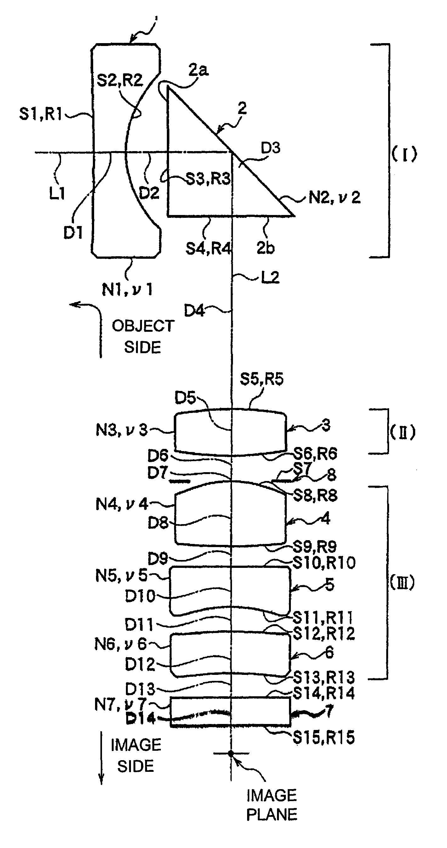
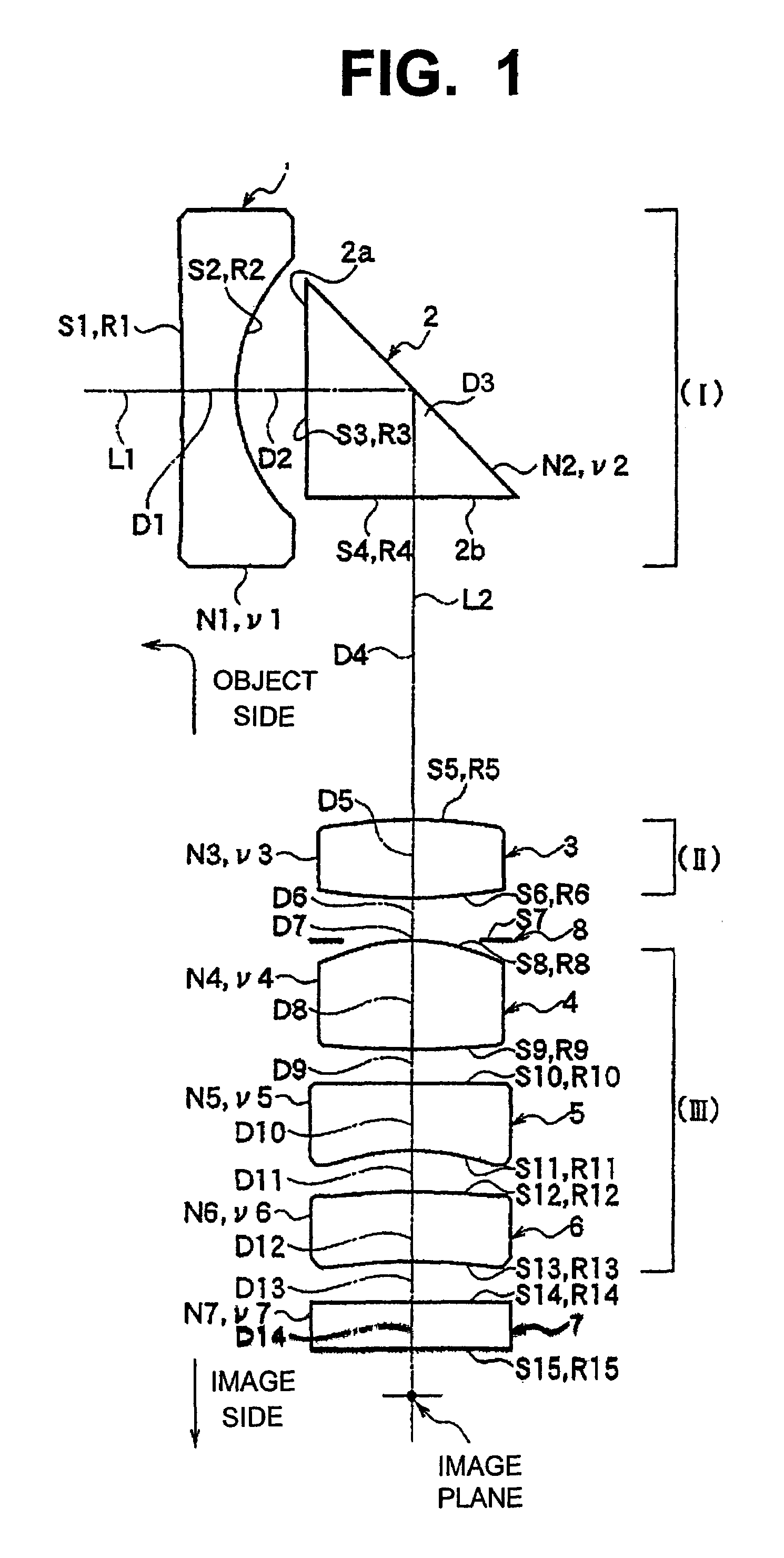
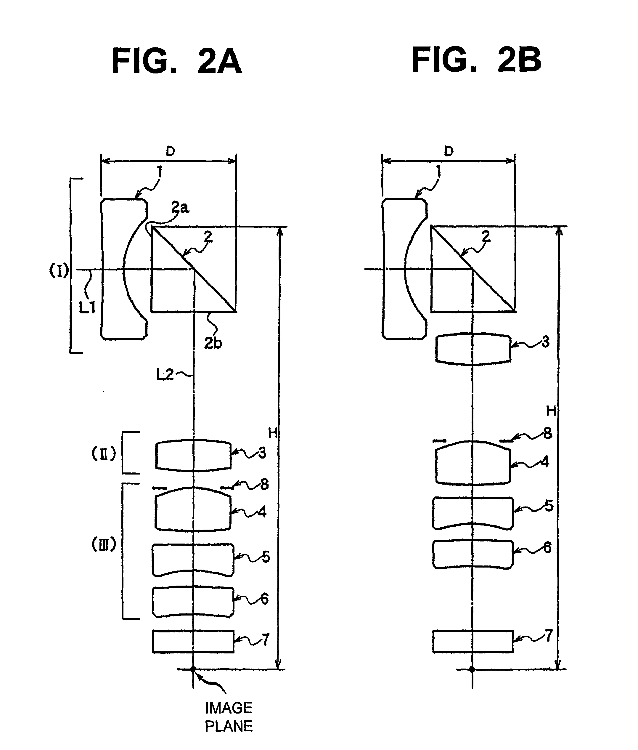
[0072]In the above embodiment 1, lens depth D (lens 1 to prism 2) is 7.75 mm, total lens length (prism to image surface) H is 25.28 mm, total lens length (front S1 of lens 1 to image surface) is 28.23 mm, back focus (air conversion) is 2.68 mm–3.99 mm–5.36 mm, F number is 2.89–3.41–3.94, and angle of view (2ω) is 61.3°–40.0°–31.1°, thus providing a compact, thin, and a high optical capability lens with all aberrations suitably corrected.

[0073]FIG. 7 and FIG. 8 show the basic constitution of a zoom lens of another embodiment according to this invention. All components of this zoom lens are made of plastics (resins) and the zoom lens is constituted similarly to the above mentioned embodiment except the changes made in the specifications of lens 4′, lens 5′ and lens 6′ of the third lens group (III).

[0074]As an example using specific numerical values of the above embodiment, an embodiment 2 will be shown below. Table 5 shows the major dimensions of embodiment 2, Table 6 shows various nu...

embodiment 2

[0080]In the above embodiment 2, lens depth D (lens 1 to prism 2) is 7.75 mm, total lens length (prism to image surface) H is 25.39 mm, total lens length (front S1 of lens 1 to image surface) is 28.34 mm, back focus (air conversion) is 2.79 mm–4.08 mm–5.42 mm, F number is 2.89–3.43–3.98, and angle of view (2ω) is 61.2°–39.9°–31.0°, thus providing a compact, thin, and a high optical capability lens with all aberrations suitably corrected.

[0081]FIG. 12 and FIG. 13 show basic constitutions of zoom lens of other embodiments according to this invention. All components of this zoom lens are made of plastics (resins) and the zoom lens is constituted similarly to the above mentioned embodiment except the changes made in the specifications of lens 4″, lens 5″ and lens 6″ of the third lens group (III).

[0082]As an example using specific numerical values of the above embodiment, an embodiment 3 will be shown below. Table 9 shows the major dimensions of embodiment 3, Table 10 shows various numer...

embodiment 3

[0088]In the above embodiment 3, lens depth D (lens 1 to prism 2) is 7.75 mm, total lens length (prism to image surface) H is 25.35 mm, total lens length (front S1 of lens 1 to image surface) is 28.30 mm, back focus (air conversion) is 2.75 mm–4.04 mm–5.37 mm, F number is 2.89–3.43–3.97, and angle of view (2ω) is 61.1°–39.9°–3 1.0°, thus providing a compact, thin, and a high optical capability lens with all aberrations suitably corrected.


PUM


Abstract

The present invention provides a small, thin, light and low cost zoom lens suitable for cellular telephones, portable information terminals, etc. In particular, it can provide a small and thin, high performance zoom lens having a zoom ratio of approximately 2, a depth of less than 9 mm in shooting and storage, a total lens length of less than 29 mm, an angle of view of approximately 61°, and a F number of 2.8 or higher providing a sufficient light, with various aberrations all suitably corrected.

Description

FIELD OF THE INVENTION[0001]The present invention relates to a zoom lens suitable for small digital still cameras, video cameras and the like equipped with image pickup devices such as CCD and the like, in particular, a zoom lens suitable for small digital still cameras, video cameras and the like built into cellular telephones, portable information terminals (PDA), etc.DESCRIPTION OF THE RELATED ART[0002]In recent years, due to remarkable technical advancements in solid state image pickup devices for uses in digital still cameras, video cameras and the like, small charge-coupled devices (“CCD”) and similar devices are developed and, with it, a demand of smaller and lighter optical systems are in great demand.[0003]In particular, there is a need for smaller and thinner optical systems to be used on cellular telephones and portable information terminals as they become smaller and thinner. The optical systems used on the cellular telephones and portable information terminals of the pr...

Claims


Application Information

Patent Timeline
Patent Type & Authority Patents(United States)
IPC IPC(8): G02B15/14G02B15/16G02B13/00G02B13/18G02B15/177
CPCG02B13/002G02B13/004G02B15/177G02B13/0065G02B13/009G02B13/0045G02B15/143507
Inventor TAKEUCHI, HOTAKA
Owner COPAL CO LTD
Why Eureka
Try Eureka