Method for evaluating a welded part

Inactive Publication Date: 2006-01-17
YAZAKI CORP
View PDF7 Cites 4 Cited by
  • Summary
  • Abstract
  • Description
  • Claims
  • Application Information

AI Technical Summary

Benefits of technology

[0007]Under such a situation, it is therefore an object of the present invention to provide a method for

Problems solved by technology

That is, a product on completion of the above inspection is not wo

Method used


Image

  • Method for evaluating a welded part
  • Method for evaluating a welded part
  • Method for evaluating a welded part

Examples


Embodiment Construction

[0041]An embodiment of the present invention will be described with reference to drawings.

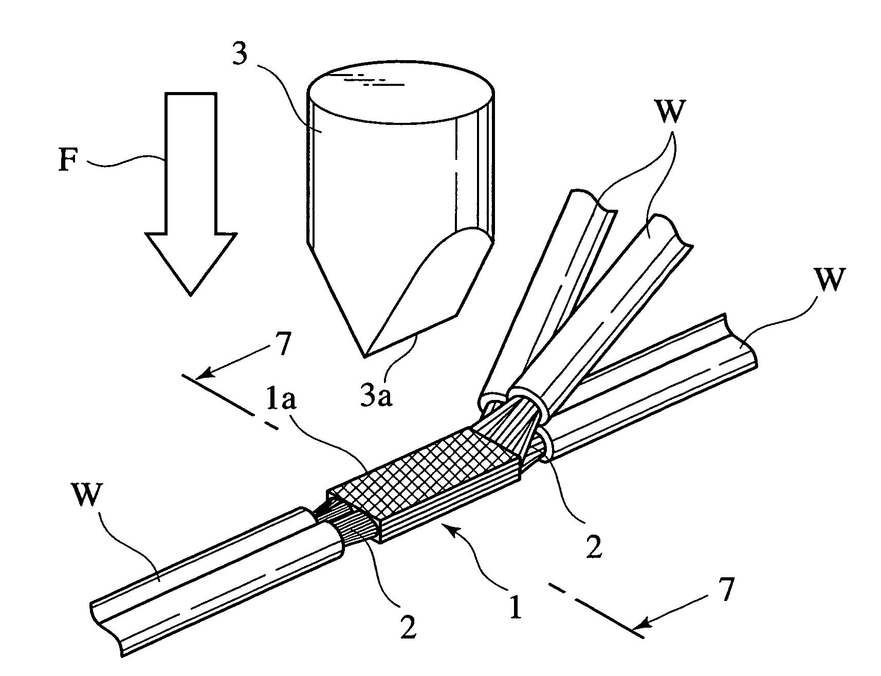
[0042]As shown in FIG. 6, a plurality of wires W are connected with each other through the intermediary of a welded part (structure) 1. This welded part 1 is completed by melting core lines 2 of the plural wires W by means of ultrasonic energy. In ultrasonic welding to form the welded part 2, the core lines 2 of the wires W are held between an ultrasonic horn and an anvil both of which are not shown in the figure and subsequently, the core lines 2 are subjected to ultrasonic vibrations. As a result, the core lines 2 are molten by ultrasonic energy, providing the welded part 1.

[0043]Next, the evaluation method of the welded part 1 will be described below. In accordance with the evaluation method, there are employed an inspection press member 3 for pressing a surface 1a of the welded part 1 to apply a compressive load F thereon, compressive-load control means (not shown) for controlling a pressur...


PUM

PropertyMeasurementUnit
Densityaaaaaaaaaa
Strengthaaaaaaaaaa
Strain pointaaaaaaaaaa

Abstract

In the method for evaluating a welded part, it is performed to make an inspection press member press the welded part for connecting a plurality of wires with each other to apply a predetermined compressive load on the welded part. Next, it is performed to measure an amount of strain of the welded part when it is subjected to the compressive load. The evaluation of the welded part in welding condition is carried out by judging whether or not the measured amount of strain is within a predetermined range.

Description

BACKGROUND OF THE INVENTION[0001]The present invention relates to a method for evaluating a welded part on production. More particularly, the present invention relates to a method for evaluating whether the welded part has a strength more than a desired strength.[0002]In a manufacturing process for electrical products, for example, there is a process of electrically connecting conductive members with each other through a welded part. Here, the producing order of such a welded part is described by one example of electrical wires as the conductive members, in brief.[0003]For instance, it is carried out to arrange respective cores of plural wires between an ultrasonic horn and an anvil and further carried out to apply a compression and ultrasonic vibrations on the cores of the wires pinched between the ultrasonic horn and the anvil. Then, the resulting ultrasonic energy allows the cores to be molten thereby producing a welded part among the cores. FIGS. 1A, 1B and 1C shows various weld...

Claims


Application Information

Patent Timeline
IPC IPC(8): G01N3/20B23K20/10B23K31/00G01N3/00G01N3/08
CPCG01N3/00G01N3/08G01N2203/0296G01N2203/0019
Inventor ICHIKAWA, HIROSHISAKAGUCHI, TADAHISAASAKURA, NOBUYUKI
Owner YAZAKI CORP
Why Eureka
Try Eureka