Radius of curvature controlled mirror

a technology of radius and curvature, which is applied in the direction of mirrors, mountings, instruments, etc., can solve the problems of not providing a perfectly spherical the desired corrective distortion of the mirror, etc., and achieves the effect of simple implementation of the radius of curvature control devi

Active Publication Date: 2006-01-17
JEFFERSON SCI ASSOCS LLC
View PDF2 Cites 8 Cited by
  • Summary
  • Abstract
  • Description
  • Claims
  • Application Information

AI Technical Summary

Benefits of technology

[0007]It is therefore an object of the present invention to provide a relatively simple to implement radius of curvature control device f...

Problems solved by technology

Among the methods commonly used to achieve such control of the radius of curvature of a mirror is that which utilizes pressure on the rear surface of the mirror while the outer periphery thereof is held in a constant position, thus resulting in the desired...

Method used


Image

  • Radius of curvature controlled mirror
  • Radius of curvature controlled mirror
  • Radius of curvature controlled mirror

Examples


Embodiment Construction

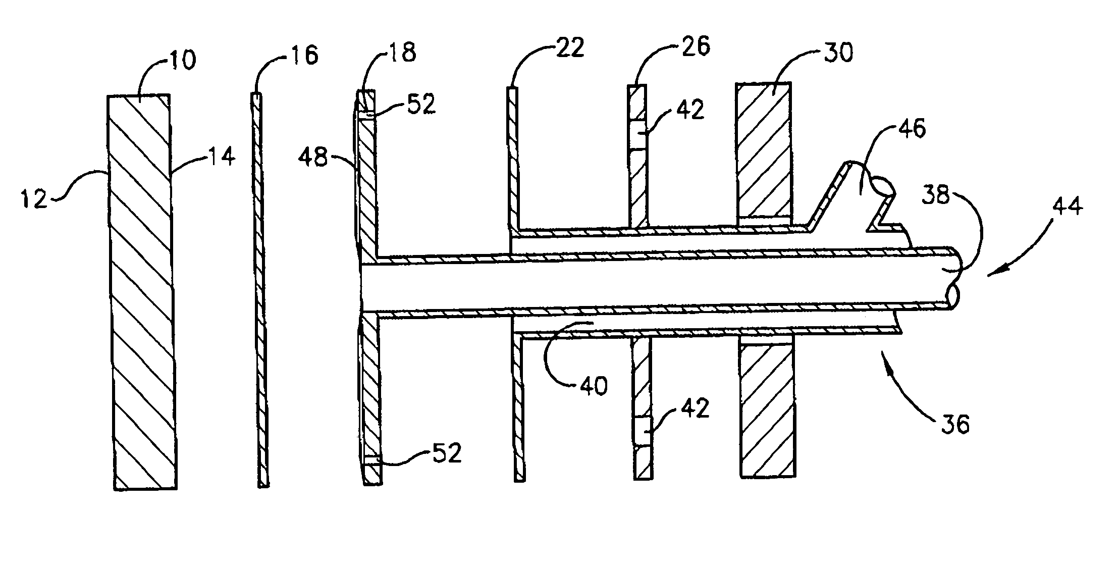
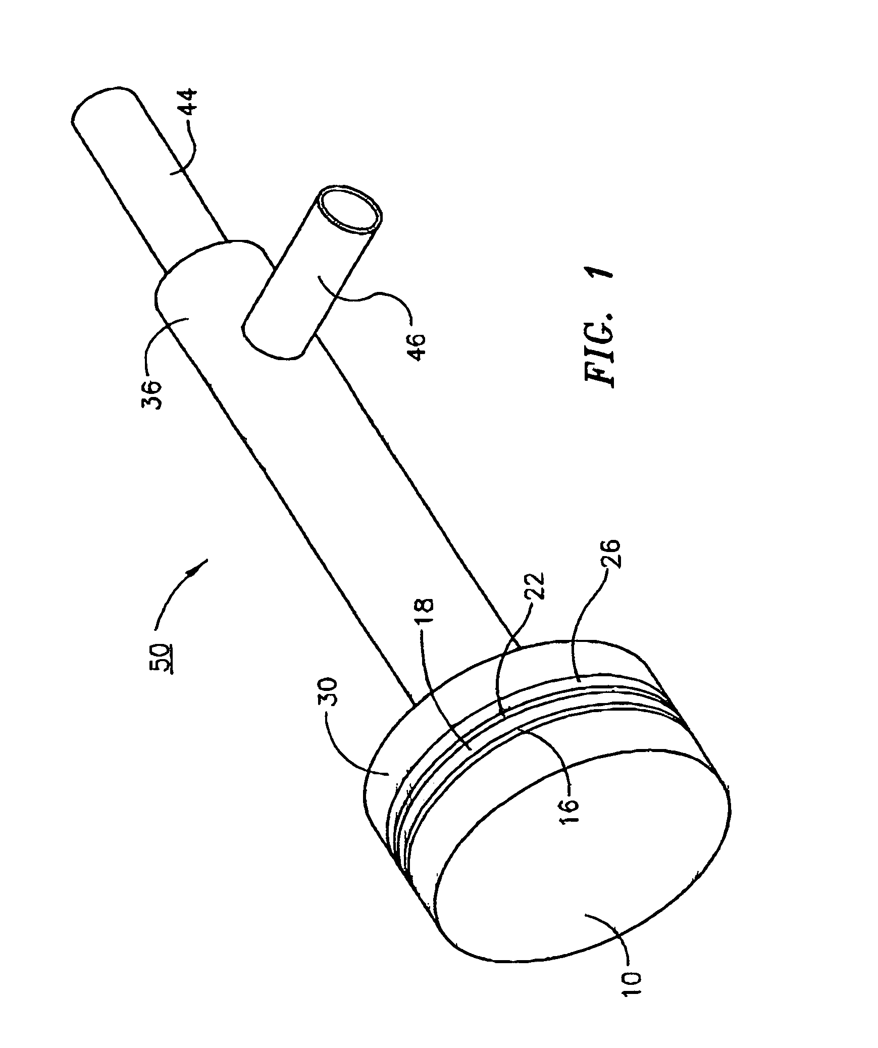
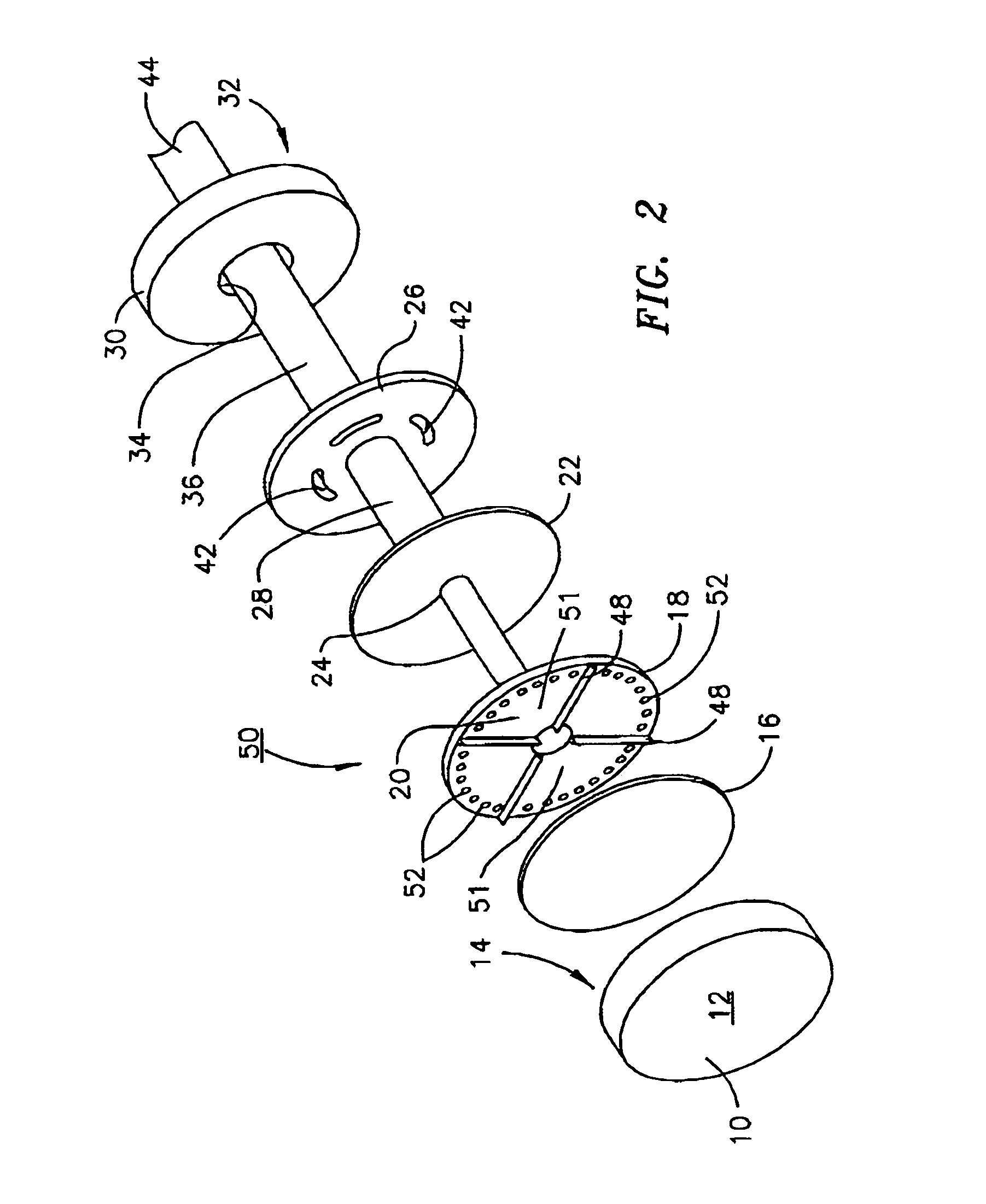
[0012]Referring now to FIG. 2, the controlled radius of curvature mirror assembly 50 of the present invention comprises bonded in order: A) a distortable mirror 10 having a reflective surface 12 and a rear surface 14; and in descending order from rear surface 14; a counter-distortion plate 16; a flow diverter 18 having a flow diverter aperture 20 at the center thereof; a flow return plate 22 having a flow return aperture 24 at the center thereof; a thermal isolation plate 26 having a thermal isolation plate aperture 28 at the center thereof and a flexible heater 30 having a rear surface 32 and a flexible heater aperture 34 at the center thereof; a double walled tube 36 defining a coolant feed chamber 38 and a coolant return chamber 40; coolant feed chamber 38 extending to and through flow diverter plate aperture 20 and terminating at counter-distortion plate 16 and coolant return chamber 42 extending to and through thermal isolation plate 26 and terminating at flow diverter plate 18...


PUM


Abstract

A controlled radius of curvature mirror assembly comprising: a distortable mirror having a reflective surface and a rear surface; and in descending order from the rear surface; a counter-distortion plate; a flow diverter having a flow diverter aperture at the center thereof; a flow return plate having a flow return aperture at the center thereof; a thermal isolation plate having a thermal isolation plate aperture at the center thereof and a flexible heater having a rear surface and a flexible heater aperture at the center thereof; a double walled tube defining a coolant feed chamber and a coolant return chamber; said coolant feed chamber extending to and through the flow diverter aperture and terminating at the counter-distortion plate and the coolant return chamber extending to and through the thermal isolation backplate and terminating at the flow diverter; and a coolant feed and a coolant return exit at the rear of said flexible heater.

Description

[0001]The United States of America may have certain rights to this invention under Management and Operating contract No. DE-AC05-84ER 40150 from the Department of EnergyFIELD OF THE INVENTION[0002]The present invention relates to apparatus for the control of curvature in mirrors and more particularly to apparatus for the control of the radius of curvature of mirrors based upon the differential expansion of dissimilar materials.BACKGROUND OF THE INVENTION[0003]It is often necessary to control the radius of curvature of a mirror to control precisely the location of the focal point, for example, in the case of the use of lasers in machining operations or to compensate for changes in other optical components due to heating of the mirror or other physical changes.[0004]Among the methods commonly used to achieve such control of the radius of curvature of a mirror is that which utilizes pressure on the rear surface of the mirror while the outer periphery thereof is held in a constant posit...

Claims


Application Information

Patent Timeline
IPC IPC(8): G02B5/08
CPCG02B5/10G02B26/0825G02B7/1815
Inventor NEIL, GEORGE R.RATHKE, JOHN WICKHAMSCHULTHEISS, THOMAS JOHNSHINN, MICHELLE D.DILLON-TOWNES, LAWRENCE A.
Owner JEFFERSON SCI ASSOCS LLC
Why Eureka
Try Eureka