Method and apparatus for light collection, distribution and zoom

a technology of light collection and distribution, applied in the field of light sources, can solve the problems of bulk and form loss, energy loss, energy loss, etc., and achieve the effect of reducing the number of light sources

Active Publication Date: 2006-01-17
SIGNIFY HLDG BV
View PDF53 Cites 80 Cited by
  • Summary
  • Abstract
  • Description
  • Claims
  • Application Information

AI Technical Summary

Benefits of technology

[0012]The central forward solid angle and the peripheral forward solid angle are demarcated from each other at approximately 0.6 π steradian solid angle centered on the optical axis of the light source. The light source comprises an LED emitter and a package in which the LED emitter is disposed. The package comprises a hemispherical front protective dome for minimizing refraction of light radiated from the LED emitter by the package. The lens is disposed longitudinally forward of the dome.
[0019]The invention is also defined as a method comprising the steps of radiating light from an LED light source, reflecting light into a first predetermined beam portion, which light is radiated from the LED light source in a peripheral forward solid angle, and focusing light into a second predetermined beam portion, which light is radiated from the LED light source in a central forward solid angle. The central forward solid angle and the peripheral forward solid angle are demarcated from each other at approximately 0.6 π steradian solid angle centered on the optical axis. Where the light source comprises an LED emitter and a package in which the LED emitter is disposed, the method further comprises the step of minimizing refraction of light radiated from the LED emitter through the package in the peripheral forward solid angle. Focusing the light into the second predetermined beam portion comprises approximately collimating the light radiated by the LED source into the central forward solid angle. Reflecting light into a first predetermined beam portion comprises approximately collimating light radiated by the LED source into the peripheral forward solid angle.

Problems solved by technology

In TIR systems, some portion of the energy radiated from the LED junction is leaked through the walls of the package and remains uncontrolled.
Additionally, there are bulk and form losses as well.
In systems with LEDs turned around to point back into a concave reflector, the center energy from the LED is shadowed by the LED package itself, so this energy is typically lost or not collected into a useful beam.

Method used


Image

  • Method and apparatus for light collection, distribution and zoom
  • Method and apparatus for light collection, distribution and zoom
  • Method and apparatus for light collection, distribution and zoom

Examples


Embodiment Construction

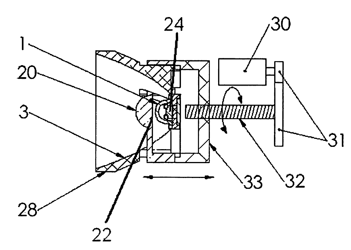
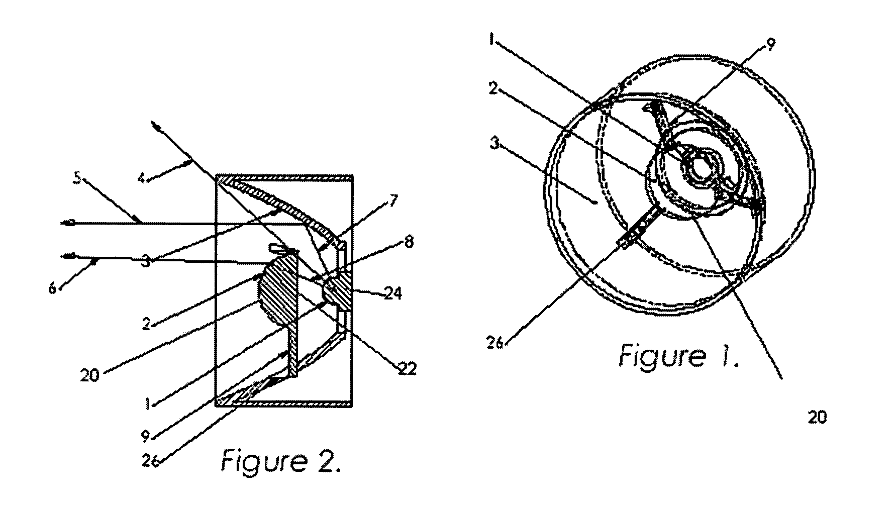
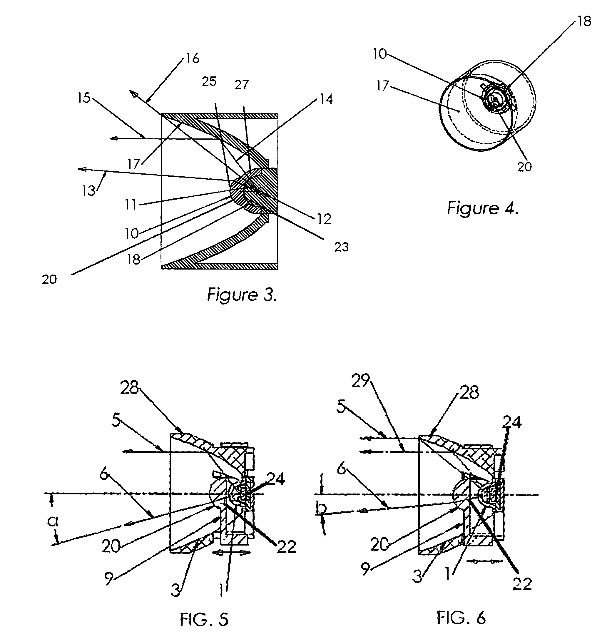
[0034]In FIGS. 1–4 a device incorporating the invention is generally denoted by reference numeral 24. LED source 1 is shown as packaged in a conventional package, which is comprised of a substrate in which the light emitting junction is defined encapsulated in a transparent epoxy or plastic housing formed to provide a front hemispherical front dome over the light emitting junction or chip. Many different types and shapes of packages could be employed by an LED manufacturer and all types and shapes are included within the scope of the invention. Hereinafter in the specification the term, “LED source 1” and in another embodiment as “LED source 18”, shall be understood to include the passivating package in which the light emitting junction or chip is housed. FIG. 1 shows a preferred embodiment of the invention in which a lens 2 is suspended over an LED source 1 by arms 9 which are attached to notches 26 in the reflector 3. It must be expressly understood that lens 2 is meant to also in...


PUM


Abstract

An LED or incandescent light source is positioned in a reflector arranged to reflect light from the LED or incandescent light source which is radiated from the LED or incandescent light source in a peripheral forward solid angle as defined by the reflector. A lens is disposed longitudinally forward of the LED or incandescent light source for focusing light into a predetermined pattern which is radiated from the LED or incandescent light source in a central forward solid angle as defined by the lens. The apparatus comprised of the combination projects a beam of light comprised of the light radiated in the central forward solid angle and peripheral forward solid angles.

Description

RELATED APPLICATIONS[0001]The present application is related to U.S. Provisional Patent Application Ser. No. 60 / 508,996, filed on Oct. 6, 2003, which is incorporated herein by reference and to which priority is claimed pursuant to 35 USC 119.BACKGROUND OF THE INVENTION[0002]1. Field of the Invention[0003]The invention relates the field of light sources using light emitting diodes (LEDs) and in particular to an apparatus and a method of collecting the energy radiating from them. The device could be used in general lighting, decorative and architectural lighting, portable and nonportable lighting, emergency lighting, fiber optic illumination and many other applications.[0004]2. Description of the Prior Art[0005]Typically in the prior art LED light source either a lens or a reflector is used to collect most of the 2π steradians front solid angle or forward hemispherical wavefront of light radiating from an LED. Recall that the solid angle Ω subtended by a surface S is defined as the su...

Claims


Application Information

Patent Timeline
Patent Type & Authority Patents(United States)
IPC IPC(8): F21V7/00F21S8/00F21S9/02F21V13/04F21V14/02F21V14/06F21V19/02H01L33/00H01L33/58H01L33/60
CPCF21S9/022F21V7/0066F21V13/04F21V14/06F21V19/02F21Y2101/02F21W2111/00F21V14/02F21Y2115/10F21S41/143F21S41/255
Inventor RHOADS, GREGHOLDER, RONALD GARRISON
Owner SIGNIFY HLDG BV
Why Eureka
Try Eureka