Optical Element

a technology of optical elements and optical coherence tomographs, which is applied in the field of optical elements, can solve the problems of difficult manufacturing and handling, the second most expensive component in some prior art systems, and the most labor-intensive component of the flexible endoscope. achieve the effect of reducing the refraction of light rays

Inactive Publication Date: 2011-07-21
OPTISCAN
View PDF40 Cites 31 Cited by
  • Summary
  • Abstract
  • Description
  • Claims
  • Application Information

AI Technical Summary

Benefits of technology

[0021]The internal surface can, optionally, have a reflective coating to increase the efficiency of reflection.
[0033]In each of the above embodiments, the external sleeve may be composed—at least where it must transmit said light and any return light—a polymer with a refractive index close to that of an expected specimen (such as, in some biological applications, PTFE, FEP, ITFE or PFA). Further, the optical element may be, filled with a liquid that has a refractive index that matches, or is close to, the refractive index of the tissue under examination, in order to minimize refraction of light rays in passing from the interior of the block to a point observational field within a specimen.

Problems solved by technology

Further, probably the most labour intensive component in the existing flexible endoscopes are the as many as 11 element micro-lens assemblies.
These lenses are so small that they are difficult to manufacture and handle, including being provided with antireflective coatings after grinding and polishing.
In addition, the second most expensive component in some prior art systems is the tuning-fork scanning mechanism.

Method used


Image

  • Optical Element
  • Optical Element
  • Optical Element

Examples


Embodiment Construction

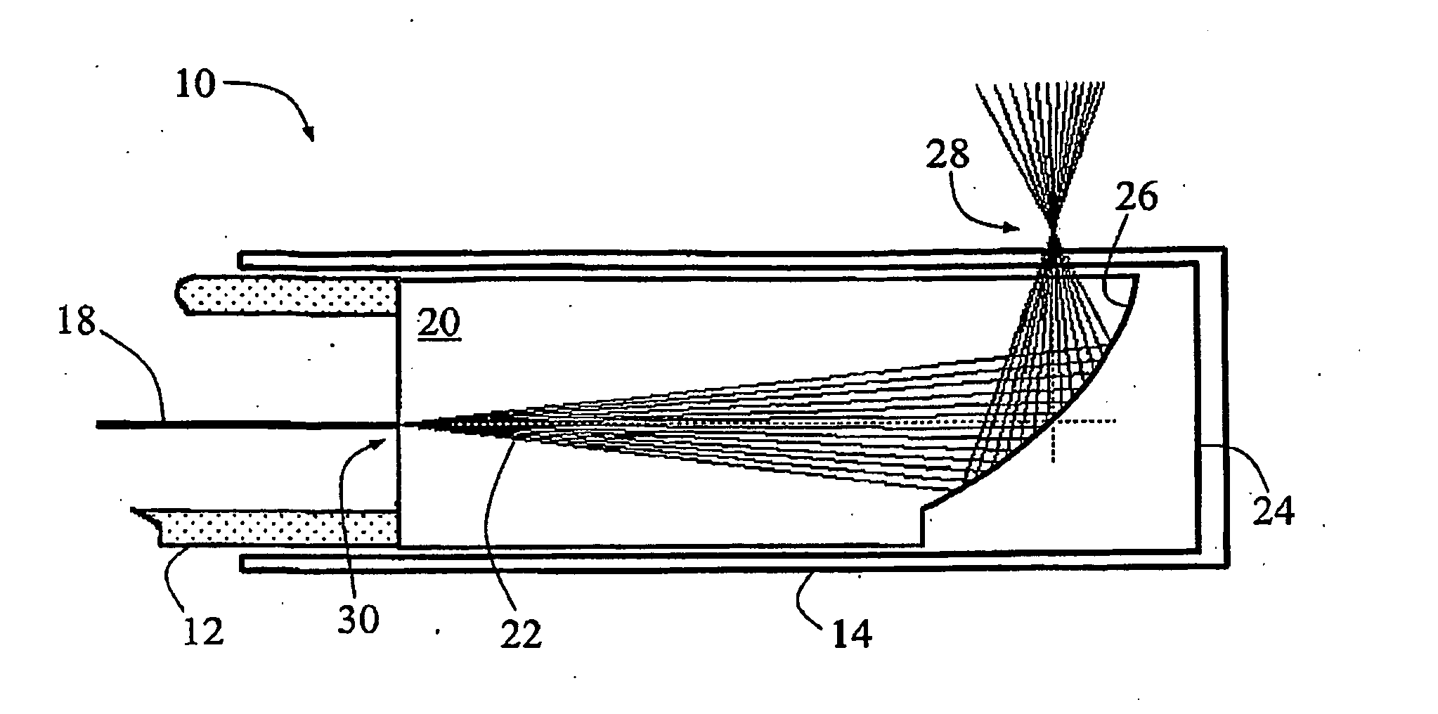
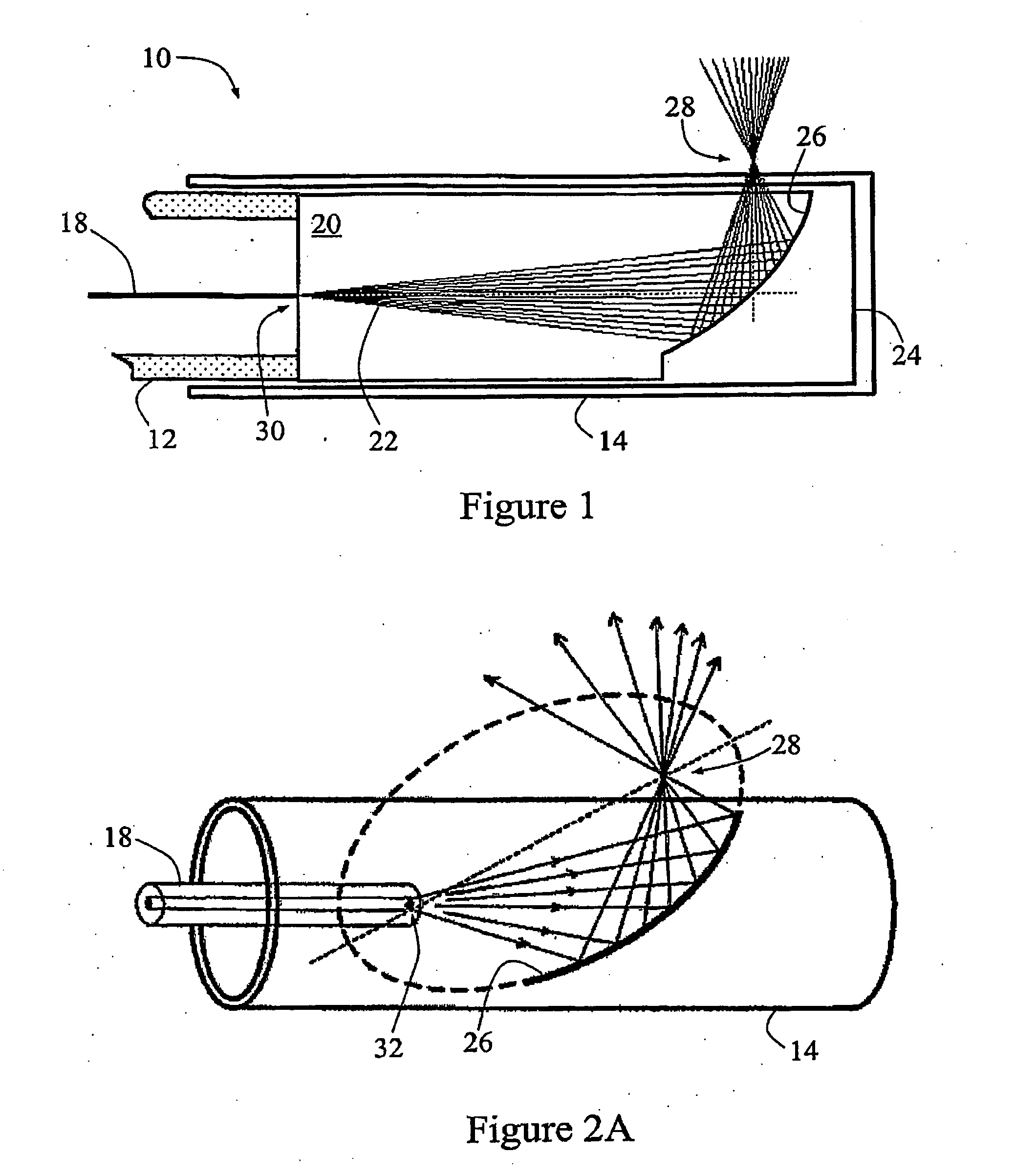
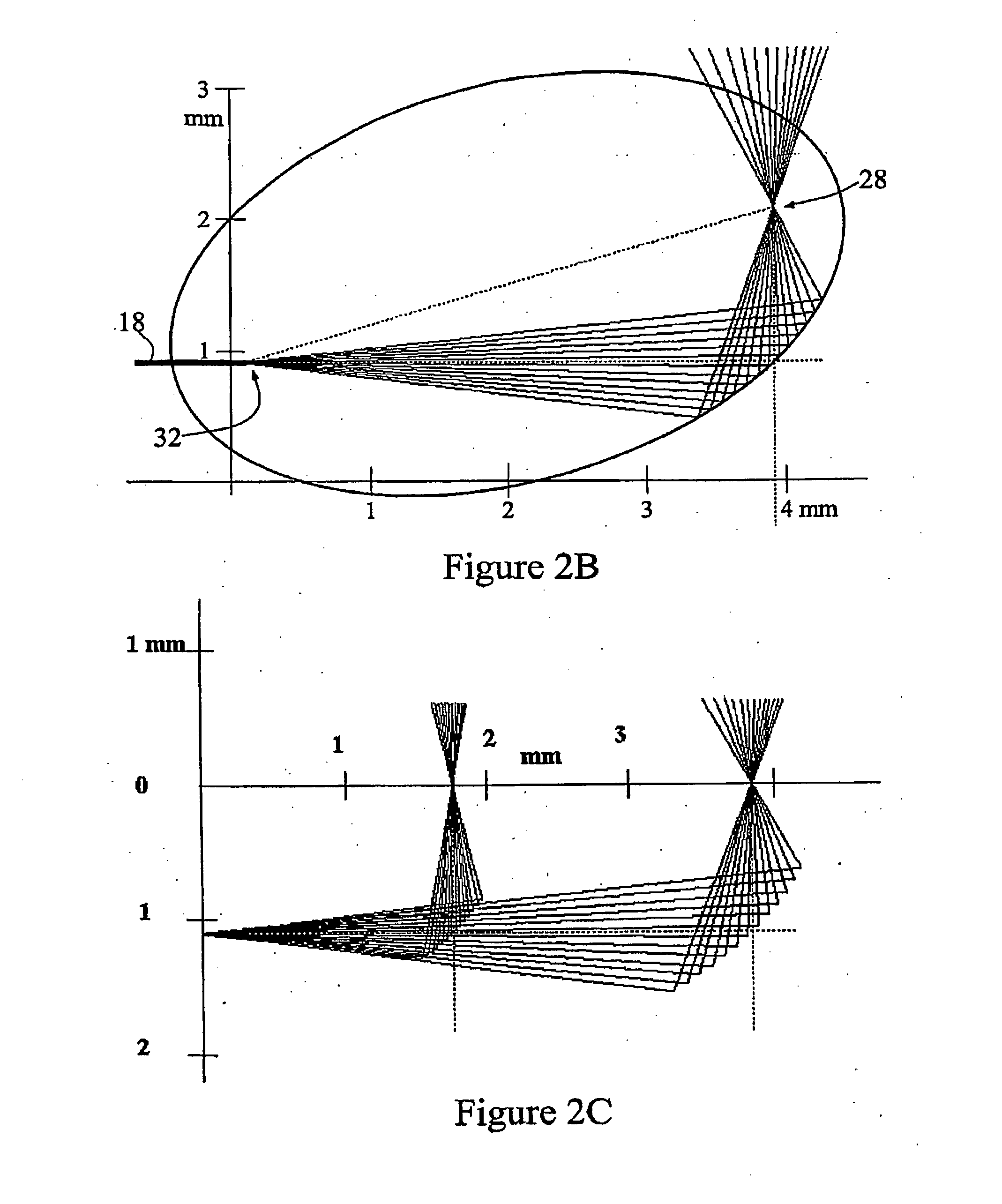
[0083]Referring to FIG. 1, according to a first embodiment of the present invention there is provided a scanning, optical head 10 for a confocal endoscope.

[0084]The head 10 has two flexible polymer tubes: a rotating inner tube 12 and a fixed cylindrical outer sleeve 14. The inner tube 12 is chosen for torsional stiffness and low coefficient of friction for contact with the external sleeve 14. The optical fibre 18 of the endoscope fits loosely within the inner tube 12, and—including its coating—has a diameter of approximately 250 micron. The inner diameter of the rotating inner tube 12 is about 1 mm; its external diameter is around 1.8 mm. The configuration of inner tube 12 with loose fibre is typical of patch cords used in optical communications systems.

[0085]The head 10 also includes an optical element in the form of a generally cylindrical plastic optical block 20, mounted on and co-rotating with inner tube 12. Optical block 20 is composed of either glass or a suitable polymer suc...


PUM


Abstract

A microscope, endoscope or optical coherence tomograph, comprising a light source, a flexible light transmitter (18) for receiving and transmitting light from the light source, an optical element (20) with a forward end (30) for receiving the light from the light transmitter (18) and a rear wall (26) having an internal surface for reflecting the light laterally, and an external sleeve (14) enclosing the optical element (20) and transparent to the light in at least a region of the sleeve where the light is directed by the internal surface (26). The internal surface (26) has an optical figure suitable for focussing the light to an observational field (28) external to the sleeve (14). A confocal configuration may be used.

Description

RELATED APPLICATION [0001]This application is based on and claims the benefit of the filing date of AU patent application no. 2004900986 filed 27 Feb. 2004, the contents of which are incorporated herein by reference in its entirety.FIELD OF THE INVENTION[0002]The present invention relates to a microscope, endoscope and optical coherence tomograph, and to an optical element for use therein, for viewing laterally, of particular but by no means exclusive application in a confocal probe as, well as in microscopy, endoscopy (including endomicroscopy), colonoscopy, gastroscopy, optical coherence tomography and like applications and especially confocal implementations and / or multi-photon variants of these.BACKGROUND OF THE INVENTION[0003]Considerable advances in imaging the interior of the human body have prompted increased interest in the possibility of in vivo microscopic analysis. Confocal microscopy using light returned from fluorescence in tissue can be achieved in an endoscope with e...

Claims


Application Information

Patent Timeline
Patent Type & Authority Applications(United States)
IPC IPC(8): A61B1/06G02B21/06A61B6/00A61B1/00A61B5/00G02B21/00G02B23/24G02B23/26
CPCA61B5/0066A61B5/0068G02B23/26G02B21/0028G02B23/2423A61B5/6852
Inventor HARRIS, MARTIN RUSSELLROSMAN, GAVAN EDMUNDVANCE, RODERICK WILLIAM CHARLESALLEN, JOHN DAVID
Owner OPTISCAN
Why Eureka
Try Eureka