Freeform optical structures for direct-lit applications

a freeform, direct-lit technology, applied in the field of optical apparatuses, can solve the problems of serious inhomogeneity in the irradiance distribution on the exit surfa

Active Publication Date: 2021-03-23
JOANNEUM RES FORSCHUNGS GMBH
View PDF8 Cites 0 Cited by
  • Summary
  • Abstract
  • Description
  • Claims
  • Application Information

AI Technical Summary

Benefits of technology

[0013]In an embodiment of the invention, the freeform optical structures are arranged to define at least one primary irradiance distribution and secondary irradiance distribution on the diffusor device, wherein the at least one primary irradiance distribution is defined by an arrangement of the plurality of light sources and a related first set of FF structures on the substrate, and wherein the secondary irradiance distributions are defined by a periodical arrangement of a second set of FF structures on the substrate in order to achieve a superposition of the secondary irradiance distributions with the at least one primary irradiance distribution. Thereby the higher proportion of unguided light which is no longer affected by the individual segments of the FF structure and overlaps with the desired homogeneous irradiance distributions on the target plane is reduced by distributing the unguided light by additional FF geometries within the secondary target areas.
[0016]In an embodiment of the invention, the apparatus further comprises a first spacer component disposed between the array of light sources and the transparent substrate to create a distance between the light sources and the transparent substrate. The first spacer provides a stable distance of the plurality of light sources to the transparent substrate thereby reducing inhomogeneity produced by mechanical stress.
[0019]In an embodiment of the invention the apparatus comprises a housing, wherein a surface of the housing is light-absorbing. A housing with a light-absorbing surface reduces scattered light within the housing.
[0021]Another aspect of the invention relates to a method for manufacturing flat freeform, FF, micro optical structures for direct-lit applications on a substrate to provide a homogenous irradiance distribution of light on a diffusor device, wherein the light is emitted by a plurality of light sources, the method comprising calculating, by an FF algorithm, a geometry of each of the plurality of FF structures on the substrate. Due to artificial intersections within the FF curves and the lateral extension of the light source, errors in the redistribution of the beams occur and result in a reduced homogeneity of the irradiance distribution within the target area. Additionally, impinging light of adjacent LEDs is overlapping with the calculated irradiance distribution. By the calculation of the FF curves, the thickness of the FF structures may be significantly decreased.
[0025]In an embodiment of the invention, calculating the geometry of the FF structures further comprises determining an upper threshold and a lower threshold of a thickness of the FF structures, the thickness being related to a maximal height of a FF curve, integrating at least one artificial intersection line into the FF curve when the FF curve drops below the lower threshold and determining a gradient of the artificial intersection line in dependence of a propagation direction of incoming rays from the light sources and the propagation direction of refracted rays inside the FF-structures to minimize light refracted by the intersection line of the FF curve. This algorithm allows the calculation of intersection lines, taking into account the propagation direction of incoming rays from the LEDs and the propagation direction of refracted rays inside the FF-structures. Thereby, the maximal height of the FF curve may be restricted during the calculation process. Light refracted by the artificial intersection lines of the FF-curve is minimized.

Problems solved by technology

This will lead to serious inhomogeneities in the irradiance distribution on the exit surface or diffusor device of the direct-lit luminaire.

Method used


Image

  • Freeform optical structures for direct-lit applications
  • Freeform optical structures for direct-lit applications
  • Freeform optical structures for direct-lit applications

Examples


Embodiment Construction

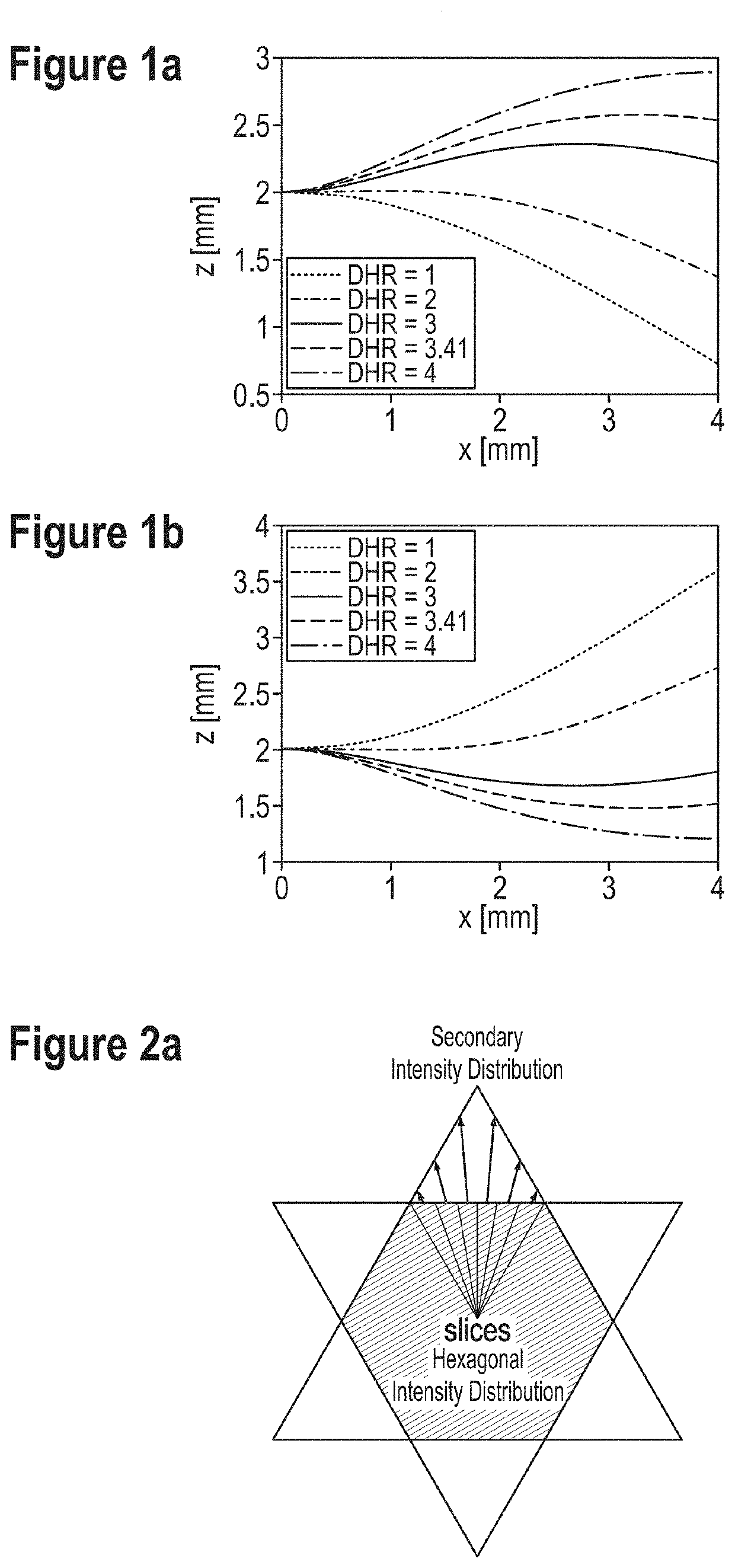
[0039]FIGS. 1a-b show a plot of resulting FF curves of structure geometries for bottom side (b) and top side (a) FF structures. FIG. 1a and FIG. 1b show FF curves for different DHR values. The FF curves shown in FIG. 1a are calculated for top side FF structures and the FF curves shown in FIG. 1b are calculated for bottom side FF structures. A bottom side structure is a structure on a side of a substrate facing the light source. FIG. 1a shows that only the FF curves with a DHR value3 have mainly negative gradients. Based on these results, the method and the apparatus according to the invention use structures located on the bottom side of the substrate or substrate foil.

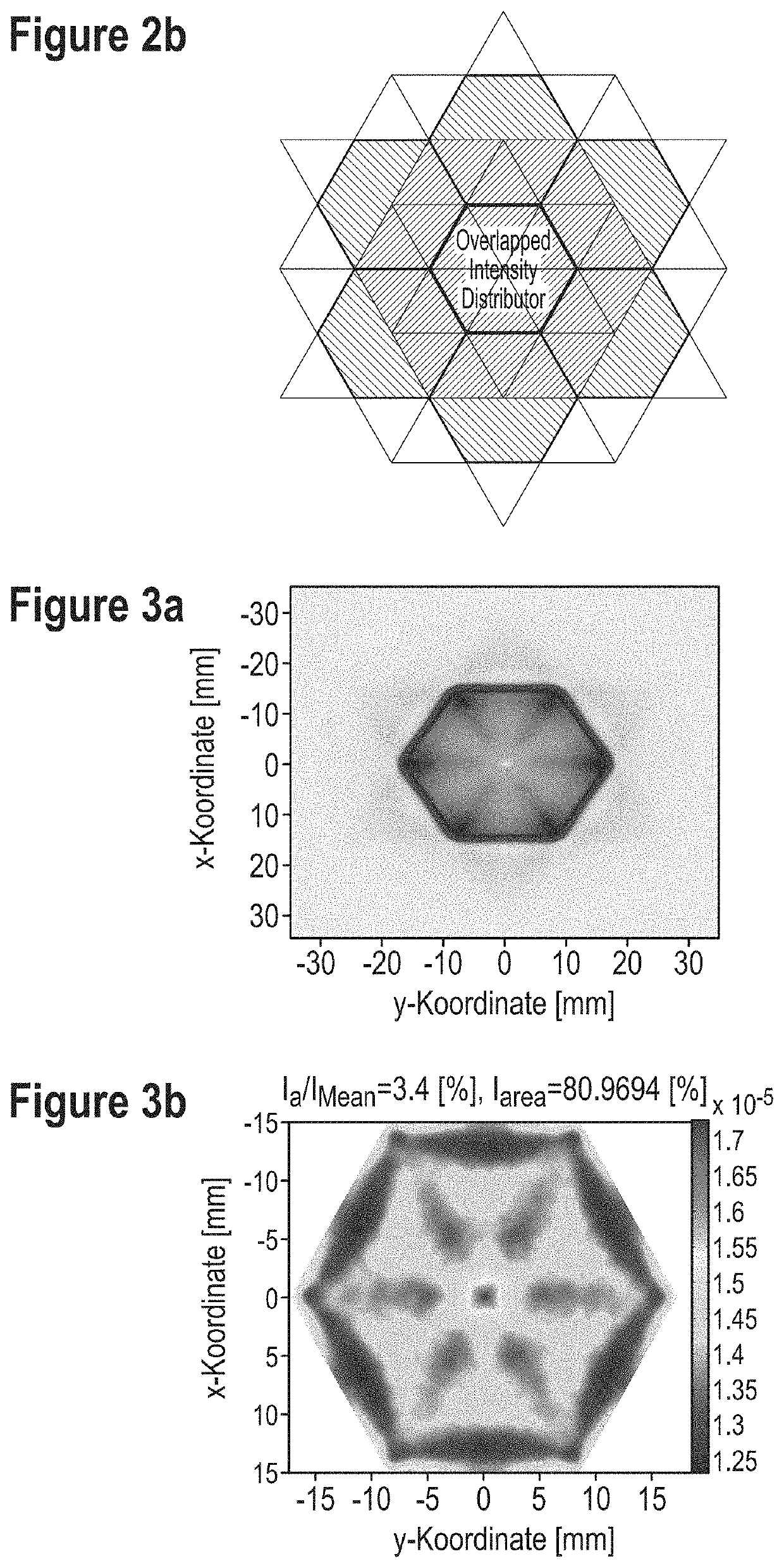
[0040]FIGS. 2a-b show a schematic representation of primary and secondary target areas for segmented FF structures with hexagonally shaped primary irradiance distributions. FIG. 2a shows that the segmented FF structure generates a hexagonal-shaped intensity distribution. Further FF geometries redistribute the intensity...


PUM

PropertyMeasurementUnit
heightaaaaaaaaaa
distanceaaaaaaaaaa
distanceaaaaaaaaaa

Abstract

An optical apparatus with a distance-to-height ratio, DHR, greater than 2, operable to emit light with a homogenized radiance distribution, the apparatus comprising a plurality of light sources, arranged in an array, a diffusor device at an exit surface of the apparatus, a transparent substrate, arranged between the plurality of light sources and the exit surface, the substrate comprising a plurality of freeform, FF, optical structures wherein the freeform structures are arranged on a bottom side of the transparent substrate facing the light sources.

Description

TECHNICAL FIELD[0001]The invention relates to an optical apparatus with a distance-to-height ratio, DHR, greater than 2, operable to emit light with a homogenized radiance distribution, the apparatus comprising a plurality of light sources, arranged in an array, a diffusor device at an exit surface of the apparatus and a transparent substrate, arranged between the plurality of light sources and the exit surface, the substrate comprising a plurality of freeform, FF, optical structures. The invention further relates to a method for manufacturing freeform optical structures.BACKGROUND ART[0002]Direct-lit luminaire systems are luminaire systems where the light of one or more light sources, arranged in an array, are directly illuminating an exit surface and / or diffusor device where the light is escaping the luminaire. Suchlike systems have applications in different fields e.g. as backlight units for liquid crystal displays (LCDs) or in general and architectural lighting. A key parameter ...

Claims


Application Information

Patent Timeline
Patent Type & Authority Patents(United States)
IPC IPC(8): G02F1/13357F21V5/00
CPCG02F1/133611F21V5/007G02F1/133602G02F1/133606G02F1/133603G02F2001/133607F21Y2115/10G02F1/133607
Inventor SOMMER, CHRISTIANLEINER, CLAUDE
Owner JOANNEUM RES FORSCHUNGS GMBH
Why Eureka
Try Eureka