
Freeform optical structures for direct-lit applications

a freeform, optical structure technology, applied in optics, lighting devices, instruments, etc., can solve the problem of serious inhomogeneity in the irradiance distribution on the exit surfa

Active Publication Date: 2019-10-17
JOANNEUM RES FORSCHUNGS GMBH
View PDF4 Cites 0 Cited by
  • Summary
  • Abstract
  • Description
  • Claims
  • Application Information

AI Technical Summary

Benefits of technology

The invention relates to a method and apparatus for manufacturing micro optical structures on a substrate for direct-lit applications. The technical effects of the invention include reducing inhomogeneity caused by mechanical stress, improving the homogeneity of the irradiance distribution on the target area, and minimizing light refracted by artificial intersection lines. The method includes calculating the geometry of each of the plurality of FF structures on the substrate using an FF algorithm, determining an upper threshold and a lower threshold of the thickness of the FF structures, and integrating at least one artificial intersection line into the FF curve. The invention allows for a more stable distance between the light sources and the transparent substrate, reducing inhomogeneity caused by mechanical stress, and provides a more uniform and homogeneous irradiance distribution on the target area.

Problems solved by technology

This will lead to serious inhomogeneities in the irradiance distribution on the exit surface or diffusor device of the direct-lit luminaire.

Method used


Image

  • Freeform optical structures for direct-lit applications
  • Freeform optical structures for direct-lit applications
  • Freeform optical structures for direct-lit applications

Examples


Embodiment Construction

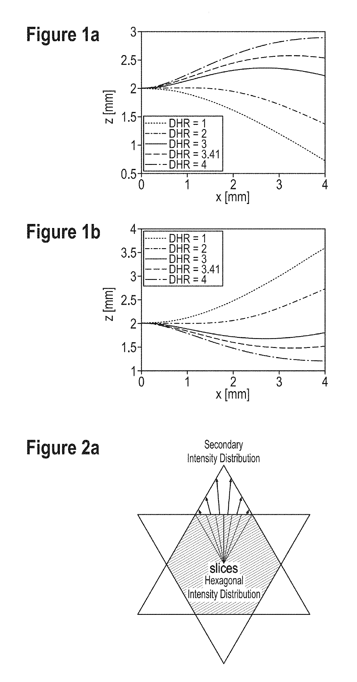
[0038]FIGS. 1a-b show a plot of resulting FF curves of structure geometries for bottom side (b) and top side (a) FF structures. FIG. 1a and FIG. 1b show FF curves for different DHR values. The FF curves shown in FIG. 1a are calculated for top side FF structures and the FF curves shown in FIG. 1b are calculated for bottom side FF structures. A bottom side structure is a structure on a side of a substrate facing the light source. FIG. 1a shows that only the FF curves with a DHR value3 have mainly negative gradients. Based on these results, the method and the apparatus according to the invention use structures located on the bottom side of the substrate or substrate foil.

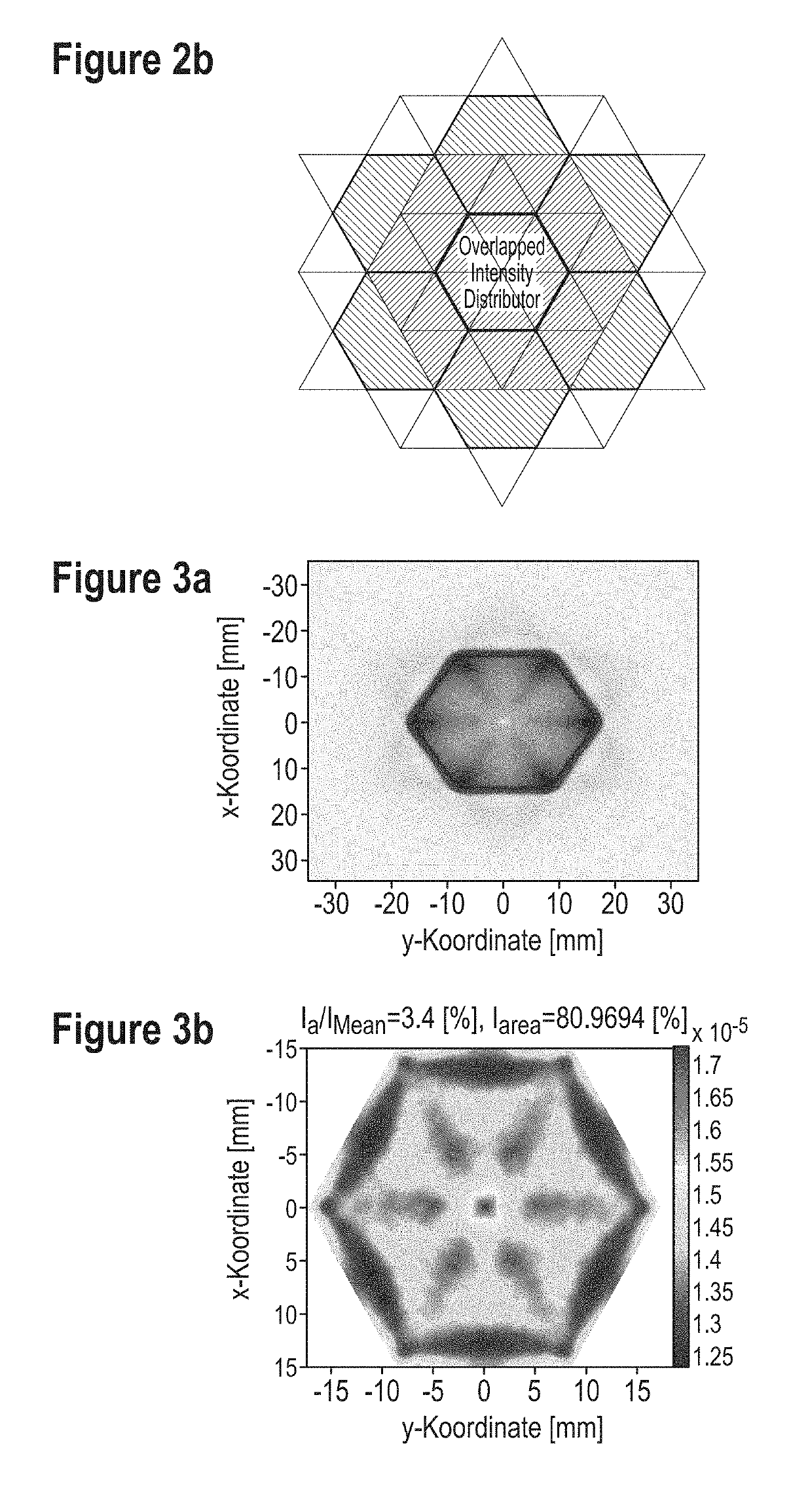
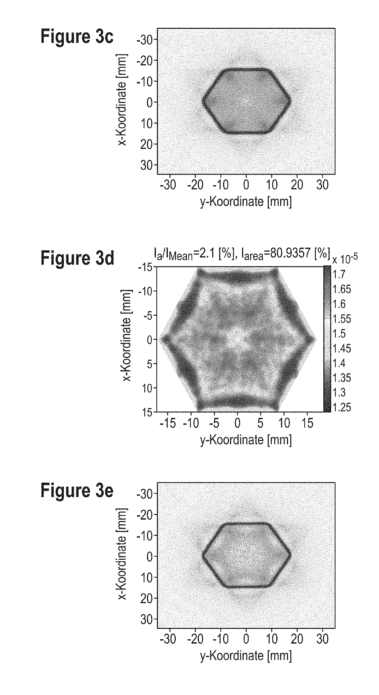
[0039]FIGS. 2a-b show a schematic representation of primary and secondary target areas for segmented FF structures with hexagonally shaped primary irradiance distributions. FIG. 2a shows that the segmented FF structure generates a hexagonal-shaped intensity distribution. Further FF geometries redistribute the intensity...


PUM

PropertyMeasurementUnit
heightaaaaaaaaaa
distanceaaaaaaaaaa
distanceaaaaaaaaaa

Abstract

An optical apparatus with a distance-to-height ratio, DHR, greater than 2, operable to emit light with a homogenized radiance distribution, the apparatus comprising a plurality of light sources, arranged in an array, a diffusor device at an exit surface of the apparatus, a transparent substrate, arranged between the plurality of light sources and the exit surface, the substrate comprising a plurality of freeform, FF, optical structures wherein the freeform structures are arranged on a bottom side of the transparent substrate facing the light sources.

Description

TECHNICAL FIELD[0001]The invention relates to a mixing or dispersing device, in particular specified for comminuting tablets and / or medicament capsules and for dissolving the comminuted tablets and / or medicament capsules in a liquid, having a vessel that has a mixing space, having a rotor that in the mixing space is drivable about a rotation axis, and having a transmission element that is capable of is coupled or is coupled to a drive, for transmitting a drive torque from the drive to the rotor. The invention relates to an optical apparatus with a distance-to-height ratio, DHR, greater than 2, operable to emit light with a homogenized radiance distribution, the apparatus comprising a plurality of light sources, arranged in an array, a diffusor device at an exit surface of the apparatus and a transparent substrate, arranged between the plurality of light sources and the exit surface, the substrate comprising a plurality of freeform, FF, optical structures. The invention further relat...

Claims


Application Information

Patent Timeline
Patent Type & Authority Applications(United States)
IPC IPC(8): G02F1/1335
CPCG02F1/133611G02F1/133606G02F1/133603F21V5/007F21Y2115/10G02F1/133602G02F1/133607
Inventor SOMMER, CHRISTIANLEINER, CLAUDE
Owner JOANNEUM RES FORSCHUNGS GMBH
Learn More