Device and apparatus for efficient collection and re-direction of emitted radiation

a technology of emitted radiation and efficient collection, applied in the field of light sources, can solve the problems of annoying bright, affecting the efficiency of beam efficiency of emitted radiation, and viewers in close proximity will be discomforted at best, and achieve the effect of minimizing refraction

Active Publication Date: 2013-03-05
SIGNIFY HLDG BV
View PDF131 Cites 0 Cited by
  • Summary
  • Abstract
  • Description
  • Claims
  • Application Information

AI Technical Summary

Benefits of technology

[0008]The central forward solid angle and the peripheral forward solid angle are demarcated from each other at approximately 45 degrees from the optical axis of the light source. The light source comprises an LED emitter and a package in which the LED emitter is disposed. The package comprises a package lens for minimizing refraction of light radiated from the LED emitter by the package. The lens is disposed around the package lens. In one embodiment the reflector is suspended in front of the package lens by means of a leg or legs or a bezel.
[0013]In a preferred embodiment of the invention since all the light from the LED is distributed into the two beams and the two beams form a composite beam treated by the secondary reflector, the secondary reflector can focus the composite beam into a beam that comprises all of the LED light that is not lost in the system to reflection and / or refraction losses and the system can deliver a very high (approximately 80%) beam efficiency of indirect light.

Problems solved by technology

Most high brightness LED optical solutions exhibit a very annoying bright LED source, such that viewers in close proximity will be discomforted at best and distracted or even temporarily ‘blinded’ when they ‘look back’ at the apparatus.
This solution, while showing better efficiency is typically less than 70% beam efficient, depending on system aperture.

Method used


Image

  • Device and apparatus for efficient collection and re-direction of emitted radiation
  • Device and apparatus for efficient collection and re-direction of emitted radiation
  • Device and apparatus for efficient collection and re-direction of emitted radiation

Examples


Embodiment Construction

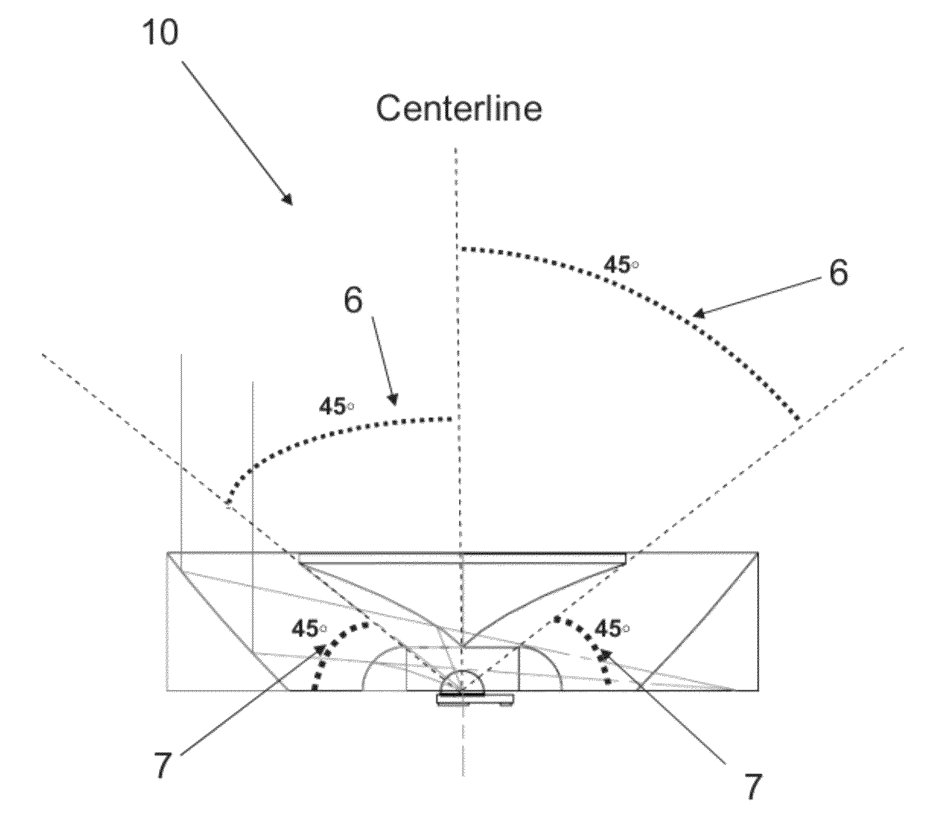
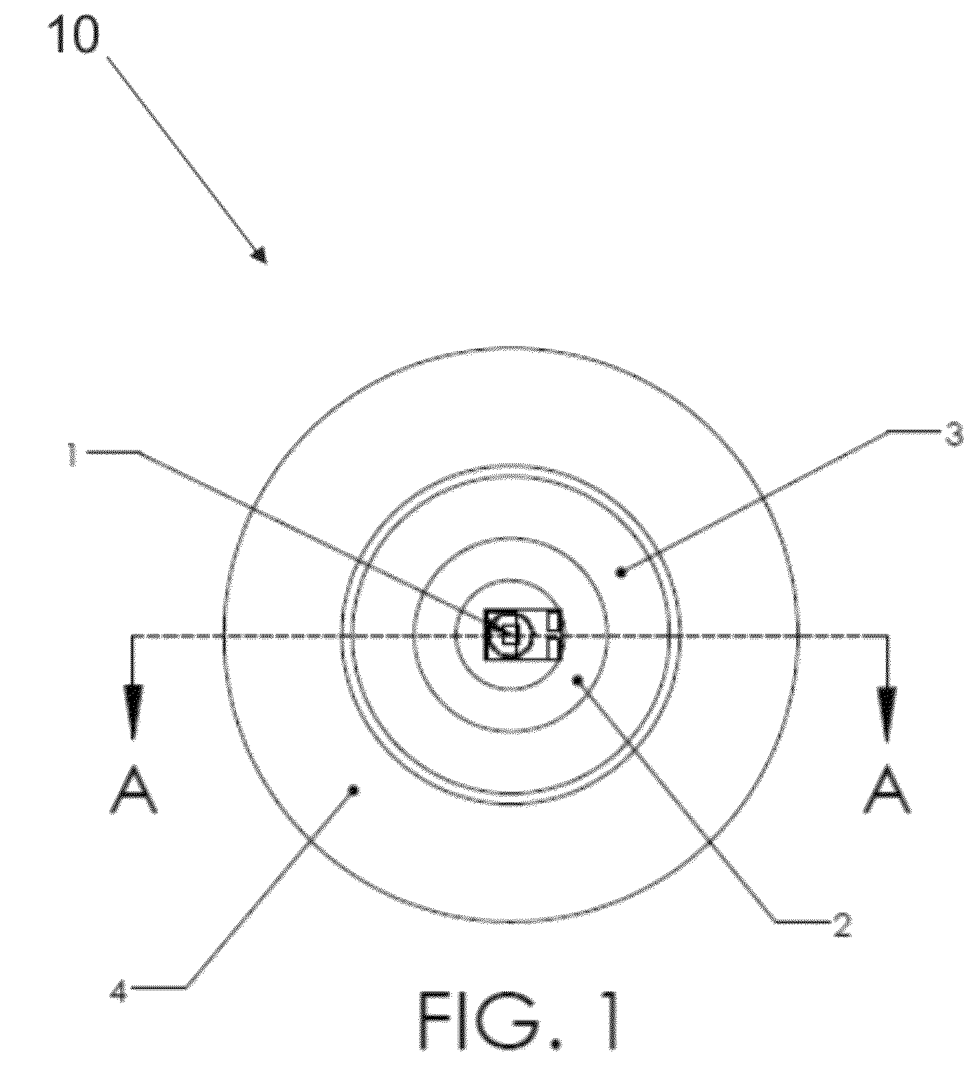
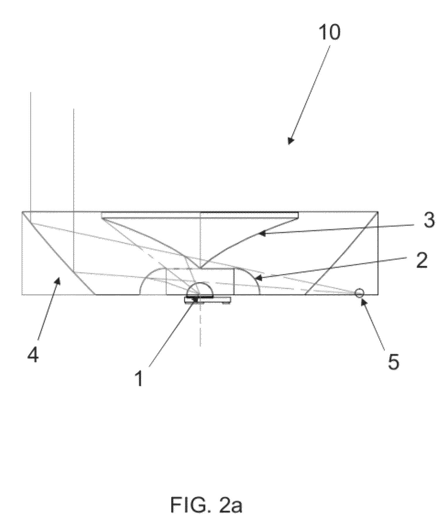
[0022]In FIGS. 1 through 3 illustrate an exemplary device 10 in accordance with the invention. LED source 1 is shown as packaged in a conventional package, which is generally comprised of a substrate in which the light emitting junction is encapsulated in a transparent epoxy or plastic housing formed to provide a hemispherical front dome or lens over the light emitting junction or chip. Many different types and shapes of packages could be employed by an LED manufacturer and all types and shapes are included within the scope of the invention. Hereinafter in the specification the term, “LED source 1.”

[0023]FIG. 1 shows a preferred embodiment of the invention in which a first reflector 3 is suspended over an LED source 1. The surface of the first reflector 3 may be specially treated or prepared to provide a highly specular or reflective surface for the particular wavelengths of light emitted by LED source 1. In the embodiment presented, the shape of the first reflector 3 is concave. Th...


PUM


Abstract

An apparatus is described, including a light source, a lens and two reflectors. A first reflector is positioned to reflect a first portion of light from the light source, wherein the first portion of light is radiated from the light source in a central forward solid angle as defined by an outer edge of the first reflector. The lens is azimuthally horizontal to the light source for accepting a second portion of light from the light source emitted in a peripheral forward solid angle. A second reflector reflects the first portion of light after reflectance from the first reflector and the second portion of light after passing through the lens in a composite beam, wherein the first reflector and the lens are configured such that the first and second portions of light behave as though they were emitted from a point source at the second reflector focus.

Description

BACKGROUND OF THE INVENTION[0001]1. Field of the Invention[0002]The invention relates the field of light sources using light emitting diodes (LEDs) and in particular to an apparatus and a method of collecting the energy radiating from them. The device could be used in general lighting, decorative and architectural lighting, portable lighting, emergency lighting and many other applications. The invention is particularly useful when direct visibility to the intense light source is undesirable, such as is the case for a dentist's patient.[0003]2. Description of the Prior Art[0004]Most high brightness LED optical solutions exhibit a very annoying bright LED source, such that viewers in close proximity will be discomforted at best and distracted or even temporarily ‘blinded’ when they ‘look back’ at the apparatus. Several optical solutions place the LED behind a forward mounted reflector that reflects outward a portion of the forward solid angle light emitted by the LED and reflects it a...

Claims


Application Information

Patent Timeline
Patent Type & Authority Patents(United States)
IPC IPC(8): F21V7/04
CPCF21V5/008F21V5/04F21V7/04F21K9/50G02B19/0028G02B19/0061F21V13/04F21Y2101/02F21Y2115/10F21K9/60
Inventor HOLDER, RONALD GARRISON
Owner SIGNIFY HLDG BV
Why Eureka
Try Eureka