Suction connector and suction catheter using the connector

a technology of suction connector and suction catheter, which is applied in the direction of valves, wound drains, mechanical devices, etc., can solve the problem that the function of releasing a negative pressure by the ventilating passage is lost only at a practically negligible level, and achieves the effect of simplifying the structure and avoiding contamination and infection

Inactive Publication Date: 2006-01-17
JMS CO LTD
View PDF11 Cites 8 Cited by
  • Summary
  • Abstract
  • Description
  • Claims
  • Application Information

AI Technical Summary

Benefits of technology

[0008]It is an object of the present invention to provide a suction connector and a suction catheter using the same in which a sucking force can be regulated sufficiently by releasing a negative pressure, scattering of fluid can be prevented surely to thus eliminate the danger of contamination and infection on an operator and assuring sanitation, and a structure is simplified to be cheap.

Problems solved by technology

Furthermore, even if the blocking plates are provided, the function of releasing a negative pressure by the ventilating passage is lost only at a practically negligible level.

Method used


Image

  • Suction connector and suction catheter using the connector
  • Suction connector and suction catheter using the connector
  • Suction connector and suction catheter using the connector

Examples


first embodiment

[0026]Hereinafter, a suction connector in the first embodiment of the present invention and a suction catheter to which the suction connector is attached will be explained with reference to FIGS. 1 to 5.

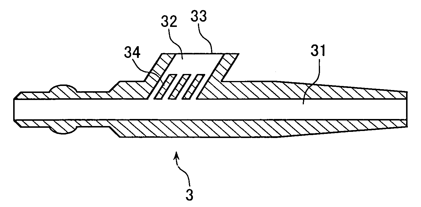
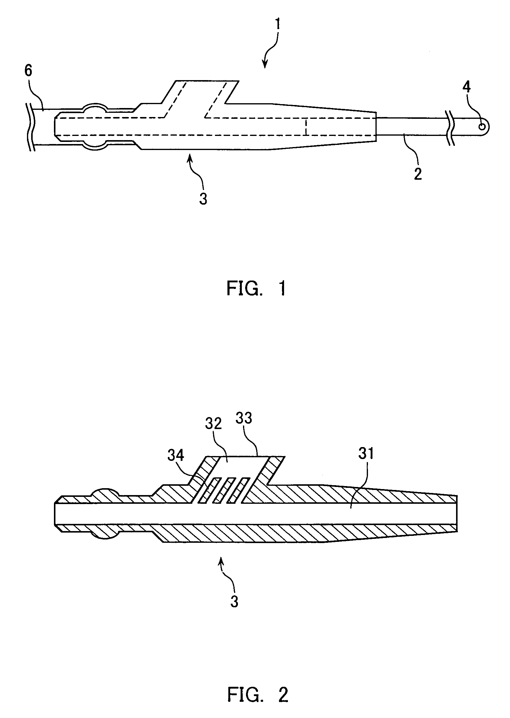
[0027]As shown in FIG. 1, a suction catheter 1 includes a flexible conduit 2 and a suction connector 3 attached to the base end side of the conduit 2. At the tip of the flexible conduit 2, one or a plurality of suction holes 4 are provided and a body fluid etc. is sucked through the hole(s). At the other end of the suction connector 3, an extension tube 6, which is to be connected to a suction source in use, can be linked.

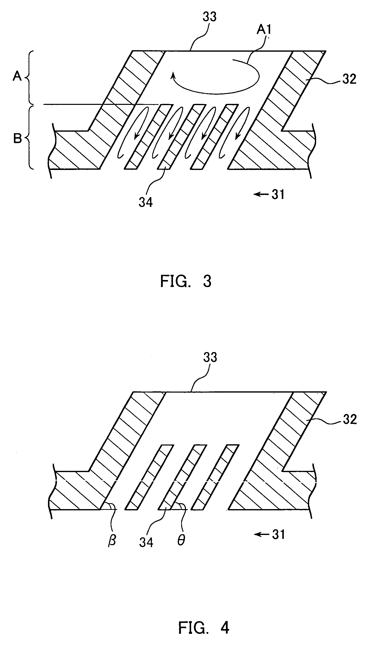
[0028]As shown in FIG. 2, the suction connector 3 includes a fluid passage 31 and a ventilating passage 32 branched in the middle of the fluid passage 31 and having an opening end 33 (suction regulating port). The ventilating passage 32 provides a function of releasing a negative pressure in the fluid passage 31. During suction, an operator adjusts the opening / closi...

second embodiment

[0037]The suction connector in the second embodiment of the present invention will be explained with reference to FIGS. 7 and 8. FIG. 7A is a plan view showing a suction connector 71 in this embodiment; and FIG. 7B is a cross-sectional view of the FIG. 7A along the line A—A.

[0038]The suction connector 71 includes a fluid passage 72 and a ventilating passage 74 branched in the middle of the fluid passage 71 and having an opening end 73 (opening portion for regulating the suction). Blocking plates 75 are provided inside the ventilating passage 74. The fluid passage 72 has a flexible conduit connecting portion 72a to be connected to a flexible conduit (not shown in the drawing) and a suction source connection portion 72b capable of being linked to an extending tube (not shown in the drawing) to be connected to the suction source. The basic operation of the suction connector 71 is the same as the suction connector 3 in the First Embodiment.

[0039]FIG. 8 is an enlarged cross-sectional vie...


PUM


Abstract

A suction connector, comprising a fluid passage (31) having one end to be connected to a conduit and the other end to be connected to a suction source when in use and a ventilating passage (32) branched in the middle of the fluid passage and having an opening end (33), wherein a blocking plate (34) is disposed at least at a partial region on a fluid passage side inside the ventilating passage, the cross-section of the ventilating passage is divided by the blocking plate into a plurality of regions, and fluid advancing from the fluid passage into the ventilating passage is prevented by the blocking plate from flowing out from the opening end, whereby a sucking force caused by an releasing a negative pressure can be regulated sufficiently, spattering of fluid can be surely prevented to thus eliminate the danger of contamination and infection to an operator and assuring sanitation, and a structure is simplified.

Description

TECHNICAL FIELD[0001]The present invention relates to a suction connector used for a medical suction catheter for sucking a body fluid etc. In particular, it relates to a suction connector capable of controlling the start and stop of suction.BACKGROUND ART[0002]A major surgery commonly is carried out under general anesthesia. At this time, in order not to induce the respiratory arrest, maintenance of the airway is carried out by inserting a tracheal catheter into the oral cavity of a patient. In such a case, in order to suppress the production of saliva, a drug such as atropine sulfate generally is administered. In order to suck and remove the saliva or sputum that is nevertheless produced, a suction catheter often is used. Furthermore, in an open-heart surgery or an abdominal operation, the suction catheter is useful for sucking and draining (and in certain cases, reusing) a body fluid such as blood or effusion, etc. coming out from an affected site such as a wound site.[0003]Howev...

Claims


Application Information

Patent Timeline
Patent Type & Authority Patents(United States)
IPC IPC(8): A61M1/00A62B9/04A61M5/00A61M27/00
CPCA61M1/0047A61M1/7411
Inventor KUMASAKI, MASAHIKOAZUKIZAWA, SHUSAKUISHIHARA, YOSHIHISA
Owner JMS CO LTD
Why Eureka
Try Eureka