Interface device for sensing position and orientation and outputting force to a user

a technology of position and orientation, which is applied in the direction of mechanical control devices, program control, instruments, etc., can solve the problems of reducing the dexterity of the user to manipulate position and orientation, preventing the use of gestures and motions, and preventing fine positioning with the fingers of the stylus

Inactive Publication Date: 2006-01-17
IMMERSION CORPORATION
View PDF208 Cites 67 Cited by
  • Summary
  • Abstract
  • Description
  • Claims
  • Application Information

AI Technical Summary

Benefits of technology

[0006]In the present invention, the user holds a stylus which is supported by a support apparatus on a fixed surface so that the user can easily manipulate the stylus in free space to interact with a computer. The three-dimensional motion of the user is translated through the stylus and mechanical linkage to a processor which communicates with the computer, thus allowing commands to be sent to the computer which track the three-dimensional motion of the user. Therefore, cursor control in three-dimensions on the two-dimensional computer screen is possible.

Problems solved by technology

While these devices allow three-dimensional information to be transmitted to a computer they do not allow the user to use gestures and motions which are natural to the user.
The use of such a stylus precludes fine positioning with the fingers and greatly reduces the dexterity of the user to manipulate position and orientation.
A button of this type is commonly called a “clicker” on a “mouse.” Because such buttons are mechanically coupled to the free-floating stylus, it is difficult to push the buttons while maintaining the position and orientation of the stylus.
Accordingly, these commands are difficult to control under many circumstances.

Method used


Image

  • Interface device for sensing position and orientation and outputting force to a user
  • Interface device for sensing position and orientation and outputting force to a user
  • Interface device for sensing position and orientation and outputting force to a user

Examples


Embodiment Construction

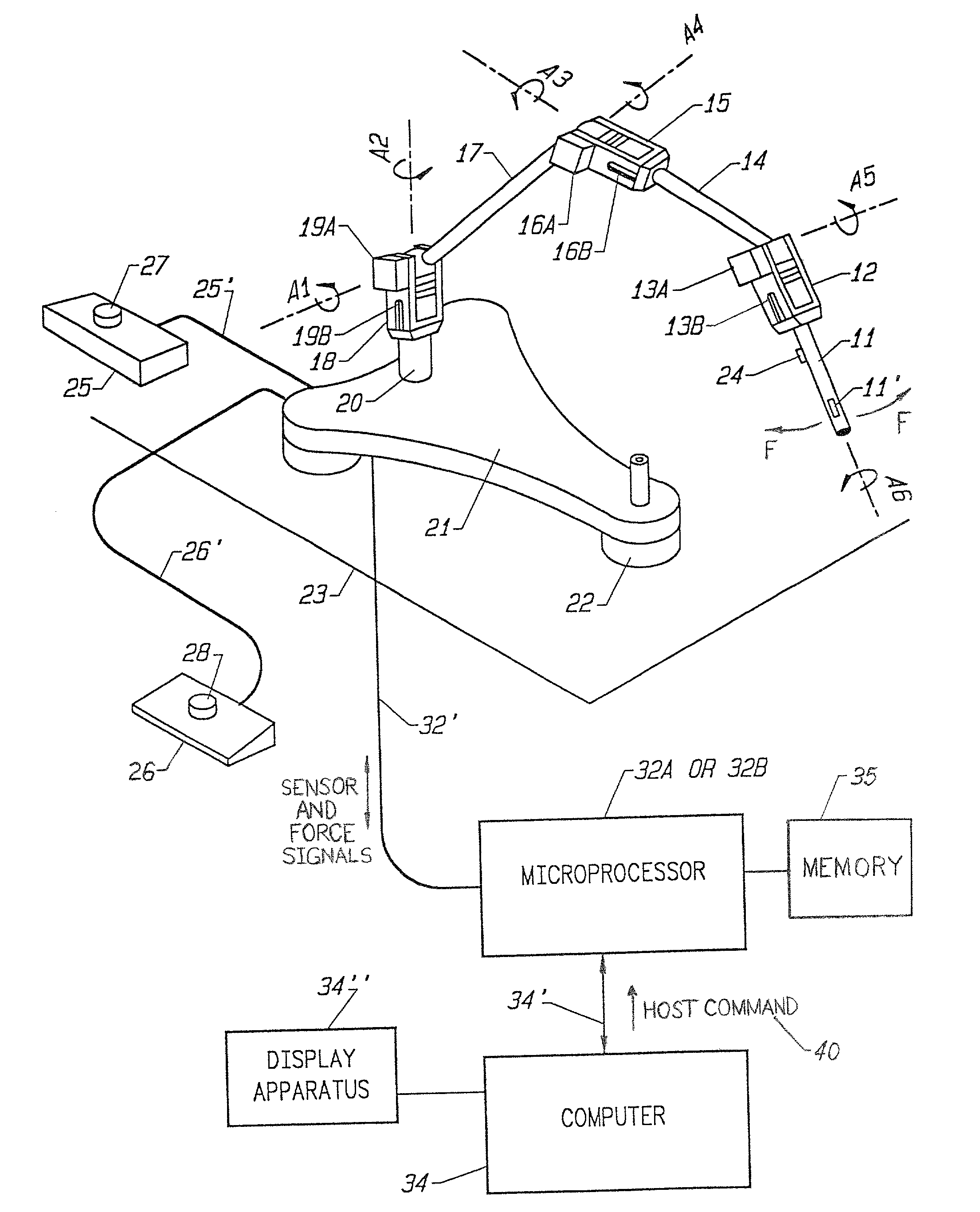
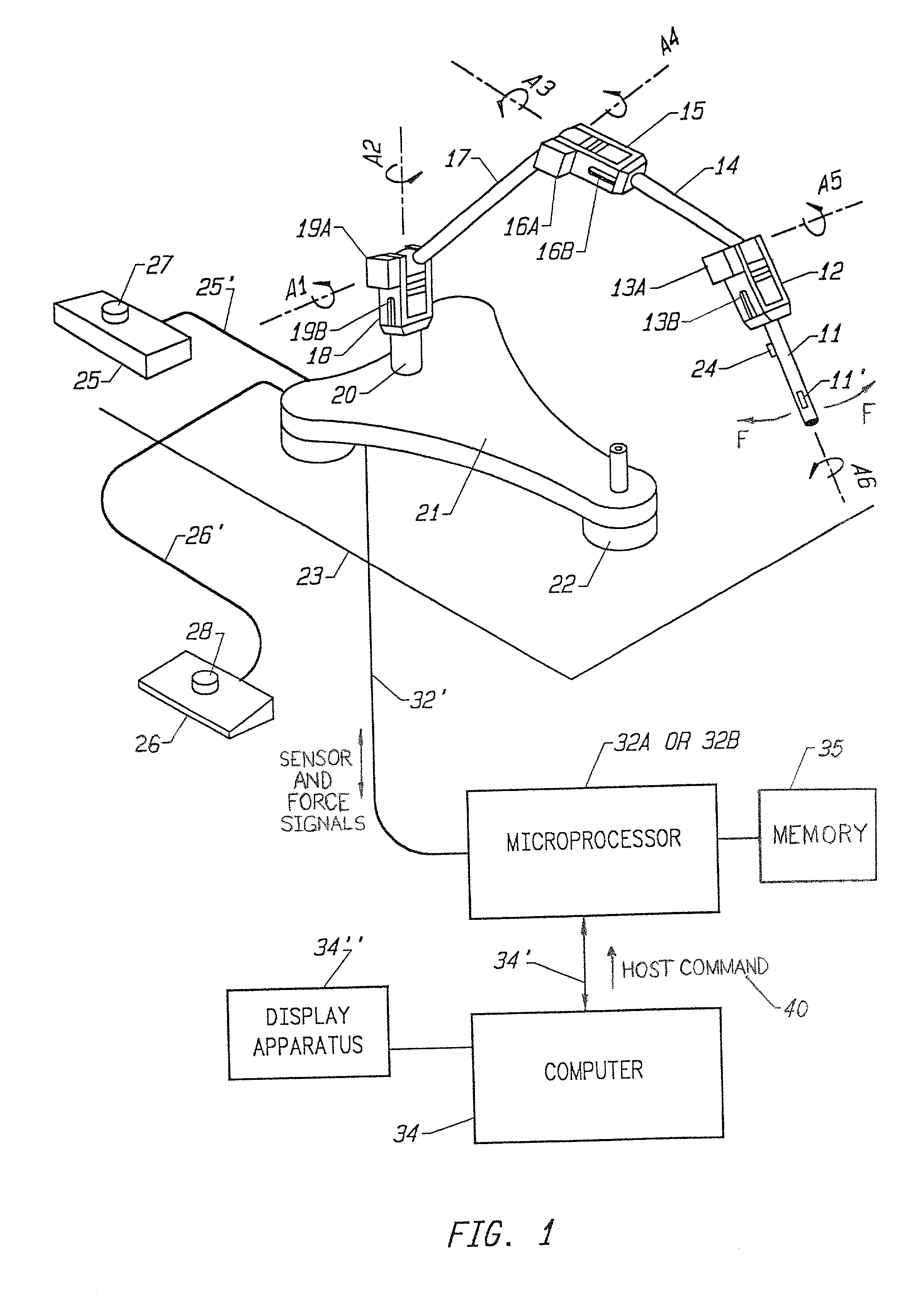
[0021]Referring to FIG. 1, a stylus 11 is shown attached to a support apparatus which is, in turn, supported on a fixed surface. By electrical and electronic configurations described below, the stylus 11 is adapted to provide data from which a computer or other computing means such as a microprocessor can ascertain the position and orientation of the stylus as it moves in three-dimensional space. This information is then translated to an image on a computer display apparatus. The stylus 11 may be used, for example, by an operator to change the position of a cursor on a computer controlled display screen by changing the position and / or orientation of the stylus, the computer being programmed to change the position of the cursor in proportion to the change in position and / or orientation of the stylus. In other words, the stylus 11 is moved through space by the user to designate to the computer how or where to move the cursor on a computer display apparatus.

[0022]Also contemplated in t...


PUM


Abstract

An interface device for use with a computer that provides locative data to a computer for tracking a user manipulatable physical object and provides feedback to the user through output forces. The physical object is movable in multiple degrees of freedom and is tracked by sensors for sensing the location and orientation of the object. A device processor can be responsive to the output of the sensors and can provide the host computer with information derived from the sensors. The host computer can provides images on a display, where the computer responds to the provided sensor information and force feedback is correlated with the displayed images via force feedback commands from the host computer.

Description

[0001]This application is a continuation of U.S. application Ser. No. 09 / 511,413, filed Feb. 23, 2000, now U.S. Pat. No. 6,366,273 which is a continuation of U.S. application Ser. No. 09 / 248,175, now U.S. Pat. No. 6,046,727, filed on Feb. 9, 1999, which is a continuation of U.S. application Ser. No. 08 / 784,198, now U.S. Pat. No. 5,880,714, filed on Jan. 15, 1997, which is a continuation of application Ser. No. 08 / 583,032, filed Feb. 16, 1996, and which issued as U.S. Pat. No. 5,701,140, which was the National Stage of International Application No. PCT / U594 / 07851, filed Jul. 12, 1994, which is a continuation of Application Ser. No. 08 / 092,974, filed Jul. 16, 1993, abandoned.FIELD OF THE INVENTION[0002]The present invention relates to a computer-human interface device, and more particularly it relates to a stylus coupled to a supportable mechanical linkage for providing and receiving commands to and from a computer.BACKGROUND OF THE INVENTION[0003]As the use of Computer Aided Design (...

Claims


Application Information

Patent Timeline
Patent Type & Authority Patents(United States)
IPC IPC(8): G09G5/00B25J9/16G01B5/008G01B7/004G01B21/04G05B19/42G05D25/02G06F3/00G06F3/01G06F3/038
CPCG01B5/008G01B7/004G01B21/04G05B19/4207G05D25/02G05G5/03G05G9/04737G06F3/011G06F3/016G06F3/0346G06F3/03545G06F3/038G06F3/0383B25J9/1692A63F2300/1037H01H2003/008G06F2203/015
Inventor ROSENBERG, LOUIS B.JACKSON, BERNARD G.
Owner IMMERSION CORPORATION
Why Eureka
Try Eureka