Eureka AIR delivers breakthrough ideas for toughest innovation challenges, trusted by R&D personnel around the world.

Method of making magnetic head having narrow pole tip and fine pitch coil

Inactive Publication Date: 2006-01-17
HITACHI GLOBAL STORAGE TECH NETHERLANDS BV
View PDF17 Cites 3 Cited by
  • Summary
  • Abstract
  • Description
  • Claims
  • Application Information

AI Technical Summary

Benefits of technology

[0011]It is an advantage of the magnetic head of the present invention that it includes a narrow, high aspect ratio P2 pole tip and a high aspect ratio, fine pitch induction coil.
[0013]It is a further advantage of the magnetic head of the present invention that it includes a narrow, high aspect ratio P2 pole tip and a high aspect ratio, fine pitch induction coil that are fabricated in a single dielectric layer.
[0014]It is an advantage of the hard disk drive of the present invention that it has an increased areal data storage density and an increased data writing rate.
[0015]It is another advantage of the hard disk drive of the present invention that it includes a magnetic head of the present invention having a narrow, high aspect ratio P2 pole tip and a high aspect ratio, fine pitch induction coil.
[0017]It is a further advantage of the hard disk drive of the present invention that it includes a magnetic head of the present invention that includes a narrow, high aspect ratio P2 pole tip and a high aspect ratio, fine pitch induction coil that are fabricated in a single dielectric layer.
[0018]It is an advantage of the fabrication method of the present invention that a narrow, high aspect ratio P2 pole tip and a high aspect ratio, fine pitch induction coil are fabricated within a single dielectric material layer.

Problems solved by technology

Prior art photolithographic techniques for fabricating P2 pole tips are currently reaching the limits of process accuracy, in that it is difficult to accurately and reliably fabricate high aspect ratio P2 pole tip trenches utilizing photolithographic techniques.

Method used


Image

  • Method of making magnetic head having narrow pole tip and fine pitch coil
  • Method of making magnetic head having narrow pole tip and fine pitch coil
  • Method of making magnetic head having narrow pole tip and fine pitch coil

Examples


Embodiment Construction

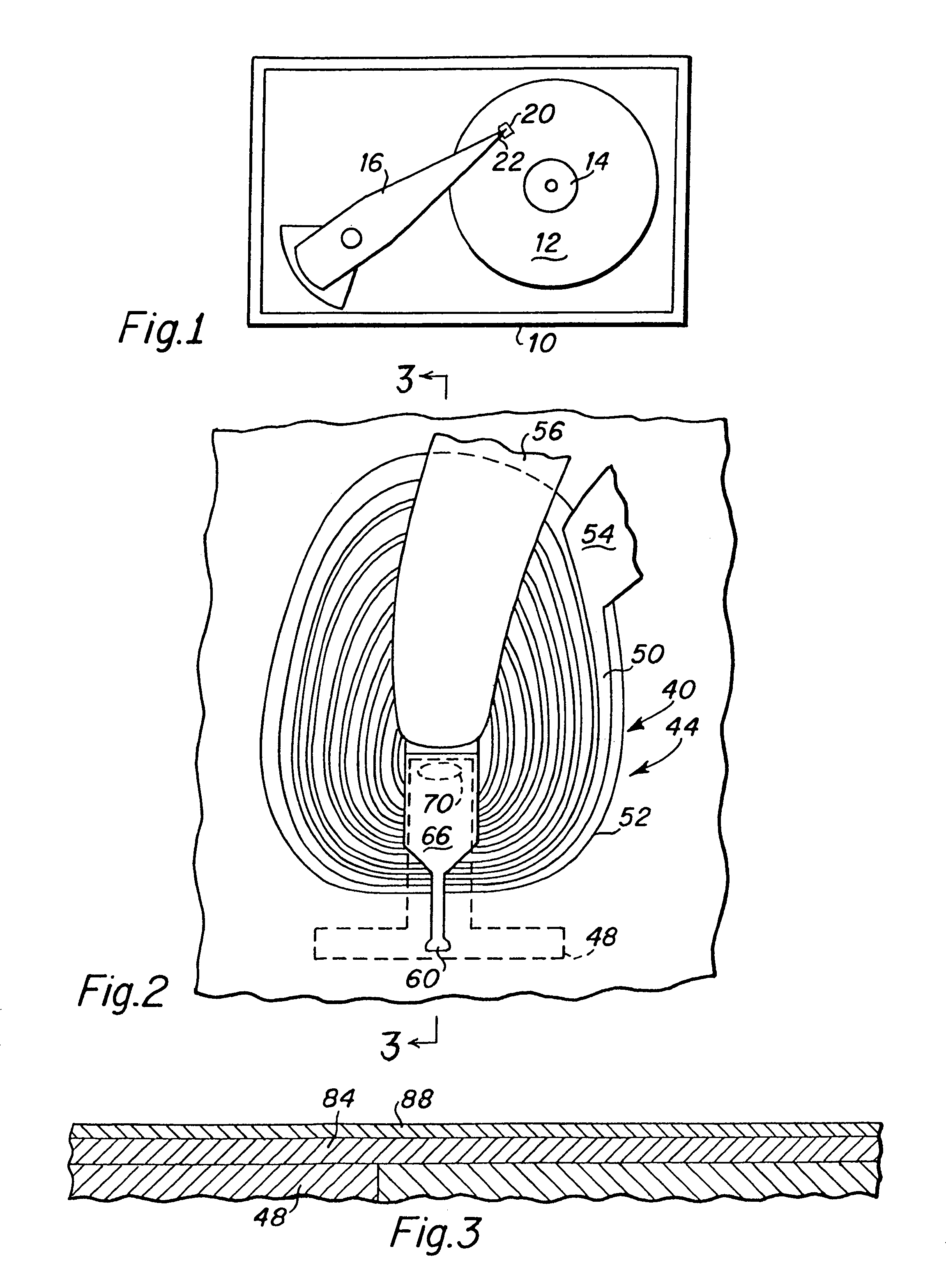
[0026]FIG. 1 is a top plan view that depicts significant components of a hard disk drive which includes the magnetic head of the present invention. The hard disk drive 10 includes a magnetic media hard disk 12 that is rotatably mounted upon a motorized spindle 14. An actuator arm 16 is pivotally mounted within the hard disk drive 10 with a magnetic head 20 of the present invention disposed upon a distal end 22 of the actuator arm 16. A typical hard disk drive 10 may include a plurality of disks 12 that are rotatably mounted upon the spindle 14 and a plurality of actuator arms 16 having a magnetic head 20 mounted upon the distal end 22 of the actuator arms. As is well known to those skilled in the art, when the hard disk drive 10 is operated, the hard disk 12 rotates upon the spindle 14 and the magnetic head 20 acts as an air bearing slider that is adapted for flying above the surface of the rotating disk. The slider includes a substrate base upon which the various structures that fo...


PUM


Abstract

Following the deposition of an insulation layer, a patterned P2 pole tip seed layer is deposited. Significantly, the pole tip seed layer is not deposited beneath the induction coil area of the magnetic head. A dielectric layer is next deposited and a patterned RIE etching mask that includes both a P2 pole tip trench opening and an induction coil trench opening is fabricated upon the dielectric layer. Thereafter, in a single RIE etching step, the P2 pole tip trench is etched through the dielectric material down to the seed layer, and the induction coil trench is etched through the dielectric material down to the insulation layer. The P2 pole tip is first electroplated up into its trench, an induction coil seed layer is next deposited, and the induction coil is then electroplated up into the induction coil trench.

Description

[0001]This is a division of application Ser. No. 09 / 884,574, filed Jun. 18, 2001, now U.S. Pat. No. 6,741,422.BACKGROUND OF THE INVENTION[0002]1 . Field of the Invention[0003]The present invention relates generally to the fabrication of magnetic heads for hard disk drives, and more particularly to the fabrication of a narrow P2 pole tip and a fine pitch induction coil using a single image transfer step.[0004]2 . Description of the Prior Art[0005]Efforts to increase the performance characteristics of hard disk drives have focused on increasing the areal data storage density of the magnetic hard disks and increasing the data writing rate of magnetic heads in writing data to the hard disks. As will be understood from reading this detailed description, the present invention advantageously affects both of these hard disk performance characteristics.[0006]One way to increase the areal data storage density is to decrease the width of the data tracks upon the hard disk media. Narrower data ...

Claims


Application Information

Patent Timeline
IPC IPC(8): G11B5/127G11B5/012G11B5/17G11B5/31
CPCG11B5/313G11B5/3163G11B5/3116G11B5/012G11B5/17Y10T29/49046G11B5/147
Inventor HSIAO, RICHARDSANTINI, HUGO ALBERTO EMILIO
Owner HITACHI GLOBAL STORAGE TECH NETHERLANDS BV
Why Eureka
Eureka Blog
Learn More