Techniques for cooling a set of circuit boards within a rack mount cabinet

Active Publication Date: 2006-01-17
EMC IP HLDG CO LLC
View PDF15 Cites 94 Cited by
  • Summary
  • Abstract
  • Description
  • Claims
  • Application Information

AI Technical Summary

Benefits of technology

[0008]In contrast to the above-described conventional electronic cabinets, embodiments of the invention are directed to techniques for mounting a data storage subsystem within a rack mount cabinet where the data storage subsystem has a fan assembly configured to generate a vertical air stream through at least a portion of the rack mount cabinet and to exhaust the vertical air stream to an external location above the rack mount cabinet. Such techniques enable manufacturers of the data storage subsystem to provide effective cooling to circuitry of the data storage subsystem (e.g., adequate cooling even in non-cold isle locations) as well to broaden the market for the data storage subsystem to the rack mount cabinet market (e.g., a market in which customers are looking to mix-and-match rack mount components within common-sized cabinets).
[0009]One embodiment of the invention is directed to a data storage subsystem for mounting within a rack mount cabinet. The data storage subsystem includes a housing configured to mount to a set of vertica

Problems solved by technology

Unfortunately, there are deficiencies to the above-described conventional electronic equipment cabinets.
For example, in connection with the above-described conventional rack mount cabinet that uses rack mount components with separate and individual horizontal air flow cooling subsystems, the cooling subsystems of the components are effective in “cold isle” locations, but loose their effectiveness in other locations that do not provide access to a reservoir of cold air at the front of the rack mount cabinet.
If these cooling subsystems are unable to adequately cool the circuitry of the rack mount components, the circuitry of such components may operate improperly or in extreme cases sustain damage due to overheating.
Such a deficiency will become m

Method used


Image

  • Techniques for cooling a set of circuit boards within a rack mount cabinet
  • Techniques for cooling a set of circuit boards within a rack mount cabinet
  • Techniques for cooling a set of circuit boards within a rack mount cabinet

Examples


Embodiment Construction

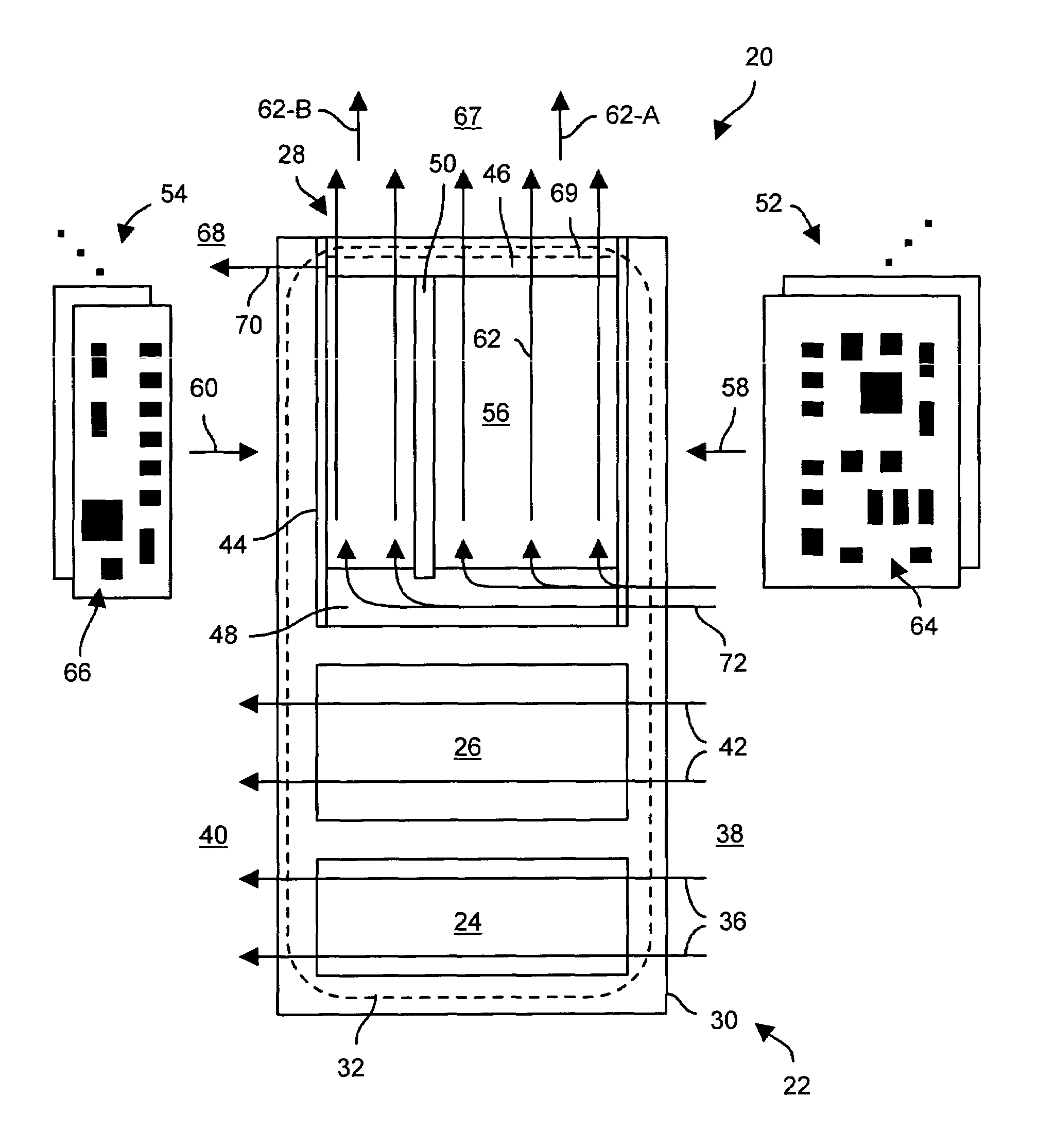
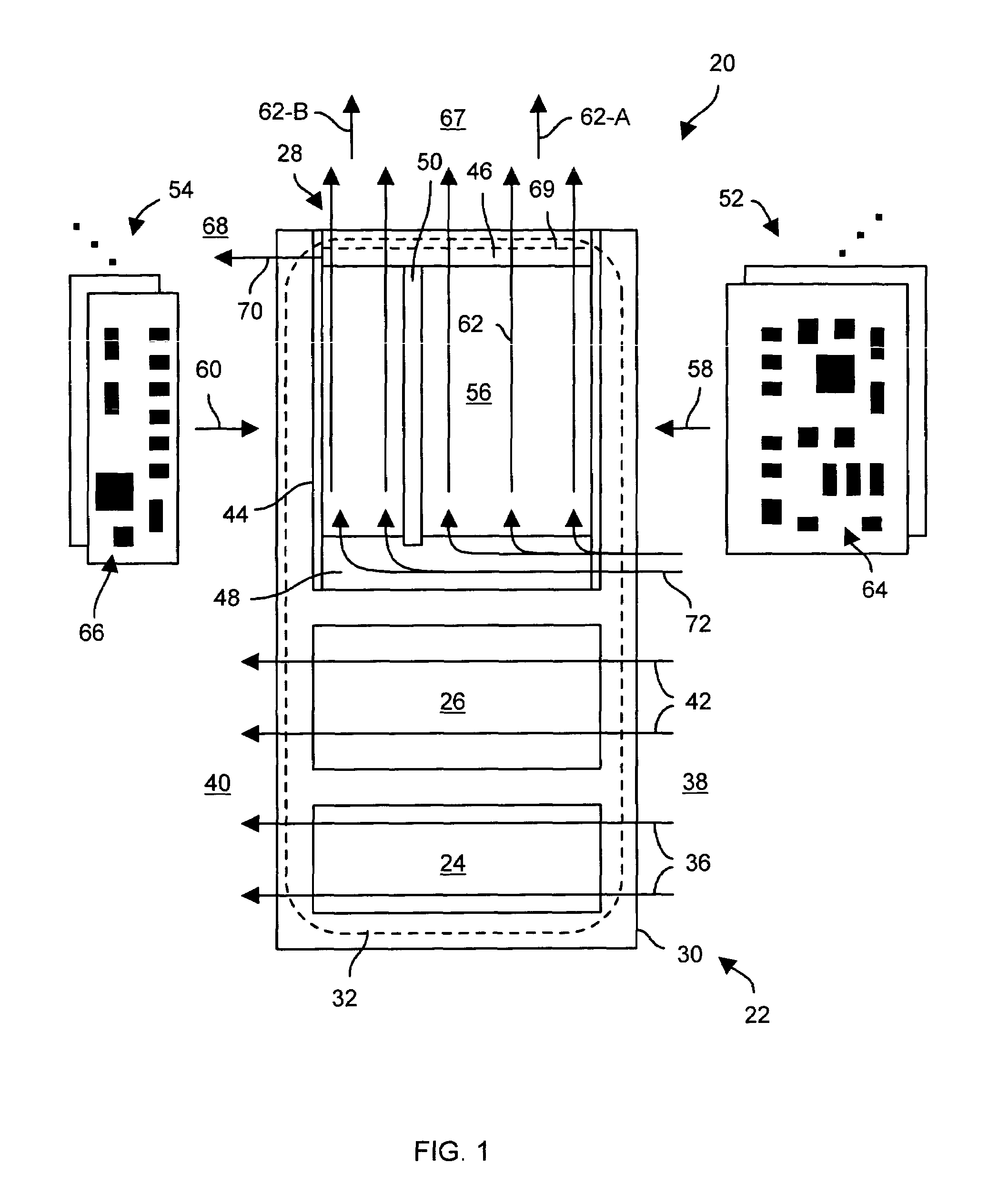
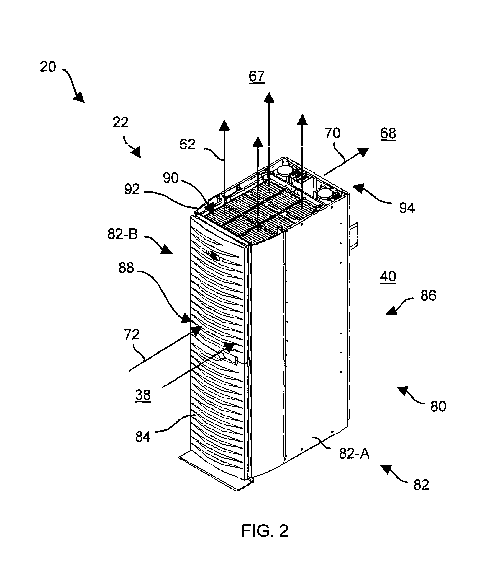
[0017]Embodiments of the invention are directed to techniques for mounting a data storage subsystem within a rack mount cabinet where the data storage subsystem has a fan assembly configured to generate a vertical air stream through at least a portion of the rack mount cabinet and to exhaust the vertical air stream to an external location above the rack mount cabinet. Such techniques enable an equipment manufacturer to provide effective cooling of circuitry of the data storage subsystem (e.g., adequate cooling even in non-cold isle locations) as well to broaden the market for the data storage subsystem to the rack mount cabinet market (e.g., a market in which customers are looking to mix-and-match rack mount components vertically within common-sized rack mount cabinets).

[0018]FIG. 1 shows a rack mount data storage system 20 which is suitable for use by the invention. The rack mount data storage system 20 includes a rack mount cabinet 22, a power supply subsystem 24, a disk drive sub...


PUM


Abstract

A data storage subsystem is configured to mount within a rack mount cabinet. The data storage subsystem includes a housing configured to mount to a set of vertical rails of the rack mount cabinet, a set of circuit boards configured to install in a vertically aligned manner within the housing to define a set of vertically oriented channels within a central space defined by the set of vertical rails of the rack mount cabinet, and a fan assembly configured to mount to the set of vertical rails in a position above the housing to generate a vertical air stream through the set of vertically oriented channels and to exhaust the vertical air stream to an external location above the rack mount cabinet. The vertical air stream enables robust heat removal from the set of circuit boards even if the rack mount cabinet does not reside in a cold-isle environment.

Description

BACKGROUND OF THE INVENTION[0001]A typical electronic equipment cabinet includes a frame and a set of panels. The frame supports electronic equipment (e.g., power supplies, backup batteries, backplanes, circuit boards, etc.). The set of panels (e.g., doors, side panels, top panels, etc.) controls access to the electronic equipment supported by the frame (e.g., protects the equipment against damage, encloses the equipment to enable fans to generate an air stream to cool the equipment, etc.).[0002]One conventional electronic equipment cabinet (hereinafter referred to as the “conventional rack mount cabinet”) includes an assembly of rigid horizontal and vertical metal beams that are fastened together to form a standard-sized frame. In particular, the metal beam assembly defines a standard width dimension for the cabinet (e.g., 19-inches) as well as defines uniformly-spaced, standard height attachment points (e.g., a standard 40-U rack) to enable vertical stacking of modularized equipme...

Claims


Application Information

Patent Timeline
IPC IPC(8): H05K7/20
CPCH05K7/20718
Inventor FRENCH, F. WILLIAMNIGRO, JR., ARTHUR ROBERT
Owner EMC IP HLDG CO LLC
Why Eureka
Try Eureka