System and method for demodulating associated information channels in direct sequence spread spectrum communications

a technology of associated information channels and spread spectrum, applied in the field of direct sequence spread spectrum (dsss) communications, can solve the problems of reducing flexibility, reducing flexibility, and reducing the efficiency of multiplexing, and achieve the effect of efficient multiplexing

Inactive Publication Date: 2006-01-17
TEXAS INSTR INC
View PDF21 Cites 4 Cited by
  • Summary
  • Abstract
  • Description
  • Claims
  • Application Information

AI Technical Summary

Benefits of technology

[0016]Specifically, each demodulating finger includes a plurality of finger channels which accept the sample stream, while providing the soft symbols of the demodulated information channels. Further, each finger channel includes a pair of parallel BPSK finger channel sections. An index section is associated with each pair of finger channels to supply a symbol index for every soft symbol. The symbols indexes are used to identify the soft symbols for subsequent multiplexing and combining operations. Using the symbol indexes, associated information channels can be efficiently multiplexed into a single information channel.

Problems solved by technology

That is, the sample stream received from two different base stations has delays that are typically much larger than multipath delays.
Hardwiring reduces flexibility, as the finger channels of the demodulating fingers must always be combined with the same partner finger channels.
Hardwiring does not permit partner finger channels to be used with different combiner channels.
However, the CPU or DSP may not have enough bandwidth to perform the combining operations, nor will such solutions prove power efficient.
Since size and power consumption are always a serious concern in the design of mobile station receivers, the complexity of the new IS-2000 standard presents the designers with the challenge of expanding receiver capabilities without dramatically increasing the receiver complexity and power consumption.

Method used


Image

  • System and method for demodulating associated information channels in direct sequence spread spectrum communications
  • System and method for demodulating associated information channels in direct sequence spread spectrum communications
  • System and method for demodulating associated information channels in direct sequence spread spectrum communications

Examples


Embodiment Construction

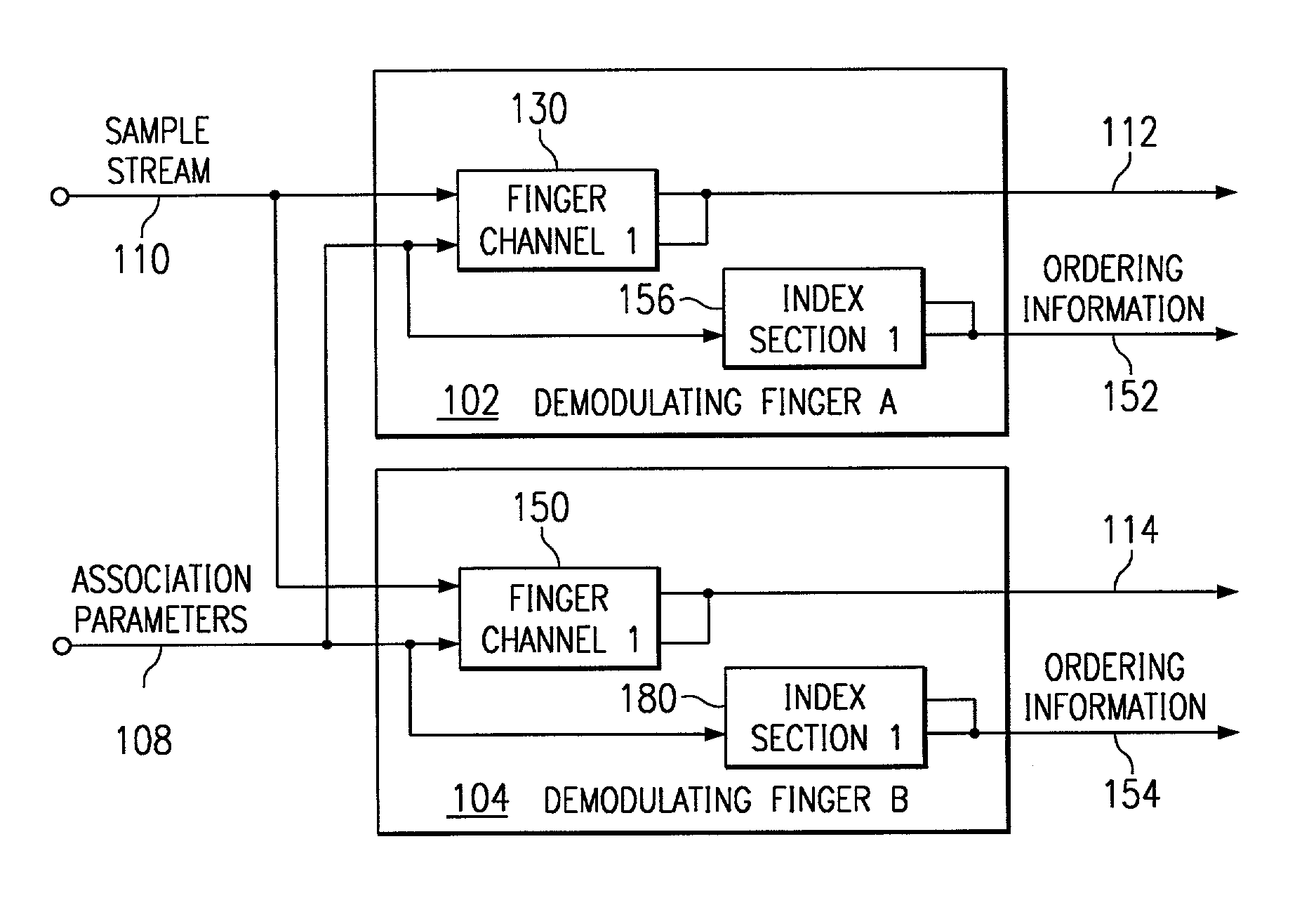
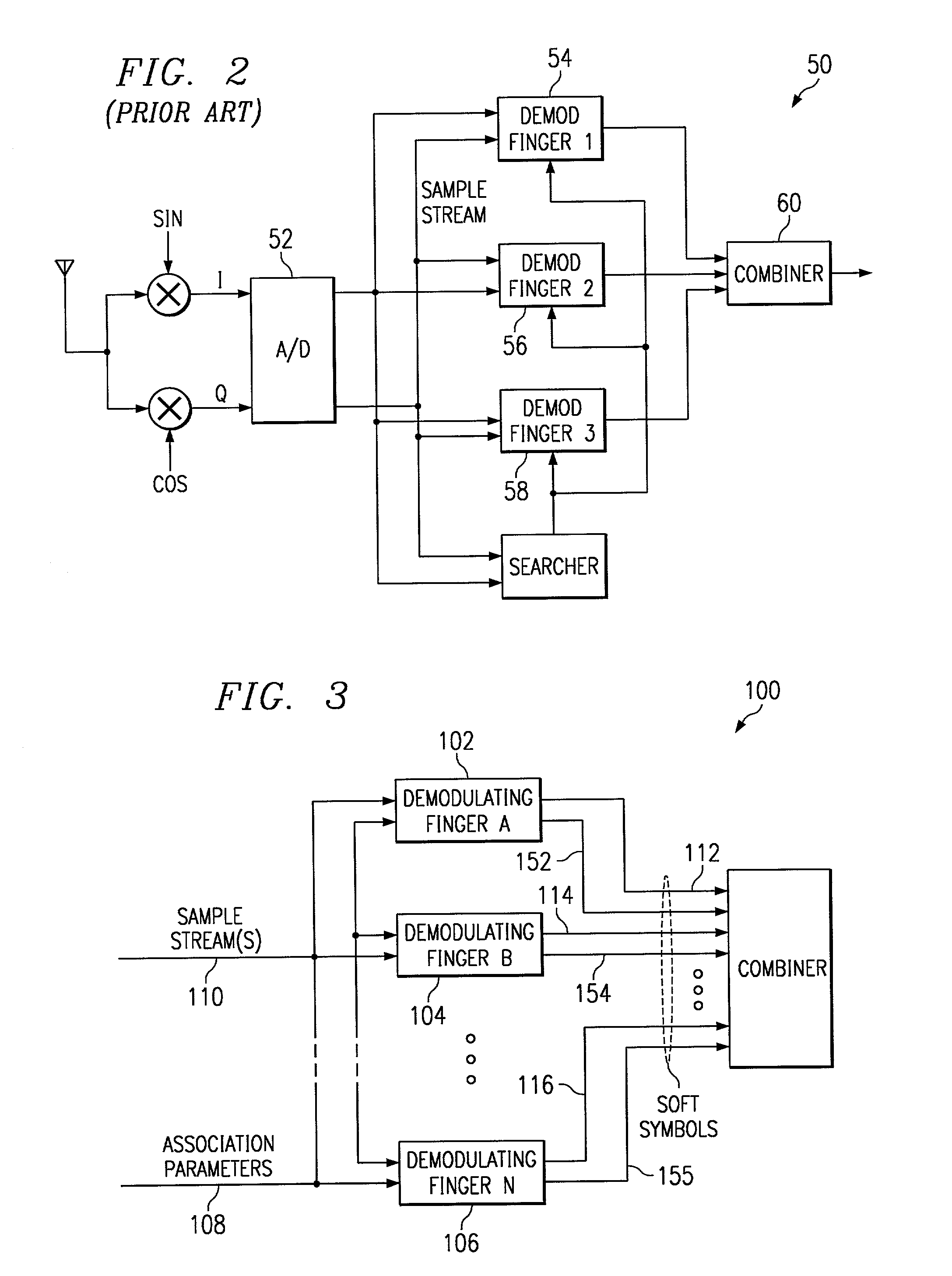
[0028]FIG. 3 is a schematic block diagram of the present invention system for demodulating a sample stream including a plurality of associated information channels in a DSSS communications receiver. The system 100 includes a plurality of demodulating fingers. Demodulating fingers A (102), B (104), up to n (106) are shown, where n can be any whole number. The invention is not limited to any specific number of demodulating fingers, but one embodiment includes n=6.

[0029]Each demodulating finger in the plurality of demodulating fingers 102–106 has a modulation parameter input on line 108 to accept modulation or association parameters and a sample stream input on line 110 to accept a sample stream. Each demodulating finger 102–106 has a soft symbol output to supply ordered soft symbols from associated demodulated information channels. Specifically, demodulating finger A (102) has a soft symbol output on line 112, demodulating finger B (104) has a soft symbol output on line 114, and demod...


PUM


Abstract

A Direct Sequence Spread Spectrum (DSSS) receiver system (100) combines and orders the soft symbols from associated information channels. The system permits a QPSK channel to be demodulated as a pair of BPSK channels, and the soft symbols of the demodulated BPSK channels to be multiplexed into a single information channel. The receiver system (100) includes a plurality of demodulating fingers (102–106). Each demodulating finger accepts modulation parameters and a sample stream, while supplying soft symbols with indexing information so that information channels can be subsequently multiplexed into a single information channel. A method for ordering the soft symbols of associated information channels in a DSSS system is also provided.

Description

FIELD OF THE INVENTION[0001]This invention relates generally to the field of direct sequence spread spectrum (DSSS) communications and, more particularly, to the demodulation of associated information channels in a code division multiple access (CDMA) RAKE receiver.BACKGROUND OF THE INVENTION[0002]In spread spectrum communications, such as in CDMA systems, pseudorandom noise (PN) sequences are used to generate spread spectrum signals by increasing the bandwidth (i.e., spreading) of a baseband signal. A forward link waveform transmitted by the base station may be comprised of a pilot waveform and a data waveform. Both of the waveforms are received with the same relative phase and amplitude distortions introduced by the channel. The pilot waveform is an unmodulated PN sequence which aids in the demodulation process, as is well-known in the art as “pilot-aided demodulation.” Conventional pilot-aided demodulation methods typically include the steps of (i) demodulating the pilot waveform...

Claims


Application Information

Patent Timeline
Patent Type & Authority Patents(United States)
IPC IPC(8): H04B1/69H04B7/216H04B1/7115H04B1/7117H04B1/712
CPCH04B1/7115H04B1/712H04B1/7117
Inventor MCDONOUGH, JOHN G.JULIAN, CRAIG M.
Owner TEXAS INSTR INC
Why Eureka
Try Eureka