System and method for deploying new equipment and services in conjunction with a legacy provisioning system

a provisioning system and legacy technology, applied in the field of communication network systems, can solve the problems of large investment in the system, complex interaction of the various points of the system, and large system capital

Inactive Publication Date: 2006-01-17
TELEFON AB LM ERICSSON (PUBL)
View PDF3 Cites 16 Cited by
  • Summary
  • Abstract
  • Description
  • Claims
  • Application Information

AI Technical Summary

Benefits of technology

[0009]The present invention is directed to systems and methods which take advantage of the realization that in legacy operations support systems the equipment is inventoried physically. It is the physical correlation of equipment (such as line cards) and the services represented by the equipment that controls the efficient operation of the system. This correlation tells the system that a piece of equipment exists in a central office or in a cabinet out in the field. It also tells the system everything the system needs to know about the proper operation of the service provided by that piece of equipment.

Problems solved by technology

These systems are complex by their very nature and often rely on a set of operation systems that sit in the back office of a carrier and control the flow of provisioning and maintenance commands that ultimately actually manage the network plant, i.e. the physical equipment.
The interaction of the various points of the system are complex and the overall invested capital in the system is large.
Looking at the evolution of carrier networks over the last 20 years, there has been little innovation in terms of how and what services are offered by these carriers.
Typically such converged products have seen little significant deployment in large carriers because their method of operation has not been compatible with the deployed back office systems due to their novel architecture.
Thus, a problem exists when it is desired to introduce into the traditional operating environment equipment and / or services which operate in a manner unknown to the legacy operations support systems.
Currently, devices and services which are not consistent with existing carrier operations support systems are being implemented by competitive local exchange carriers (CLECs), many of which have failed.
In fact, one reason for such failures could possibly be that the CLECs were unable to scale their businesses because they did not employ robust operations support systems.
If the back-office can not support scaling, it might be able to introduce new devices and services quickly, but at the expense of loss of management control, which would include installation, maintenance, trouble locating and billing.

Method used


Image

  • System and method for deploying new equipment and services in conjunction with a legacy provisioning system
  • System and method for deploying new equipment and services in conjunction with a legacy provisioning system
  • System and method for deploying new equipment and services in conjunction with a legacy provisioning system

Examples


Embodiment Construction

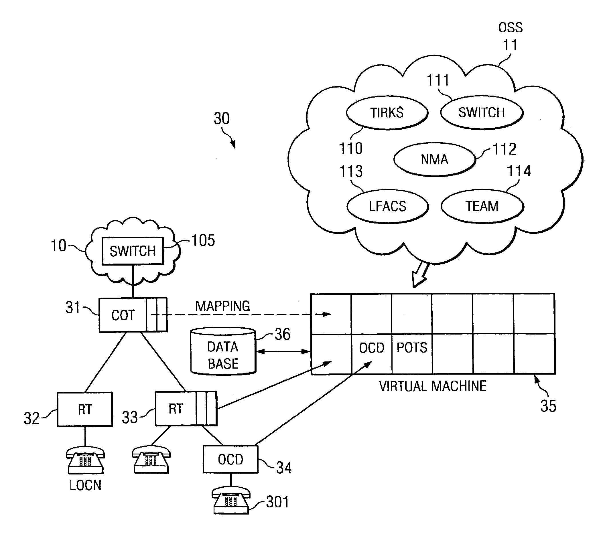
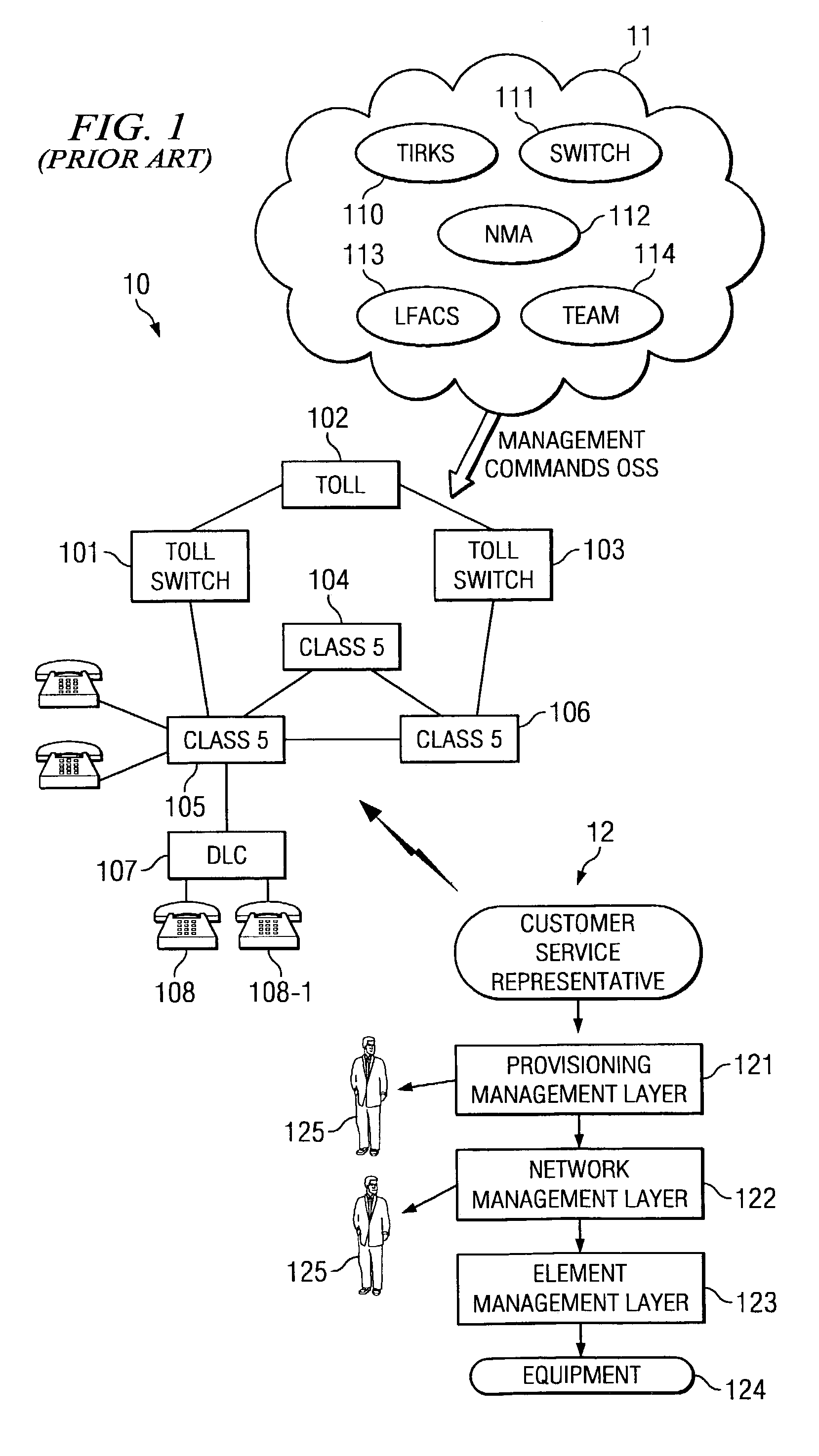
[0025]FIG. 1 is an overview of a prior art legacy operations support system and shows three distinct aspects; namely physical apparatus 10 of the network, the operations support systems 11 which manage network 10; and flow 12 which shows the operation of the system from customer service to actual equipment.

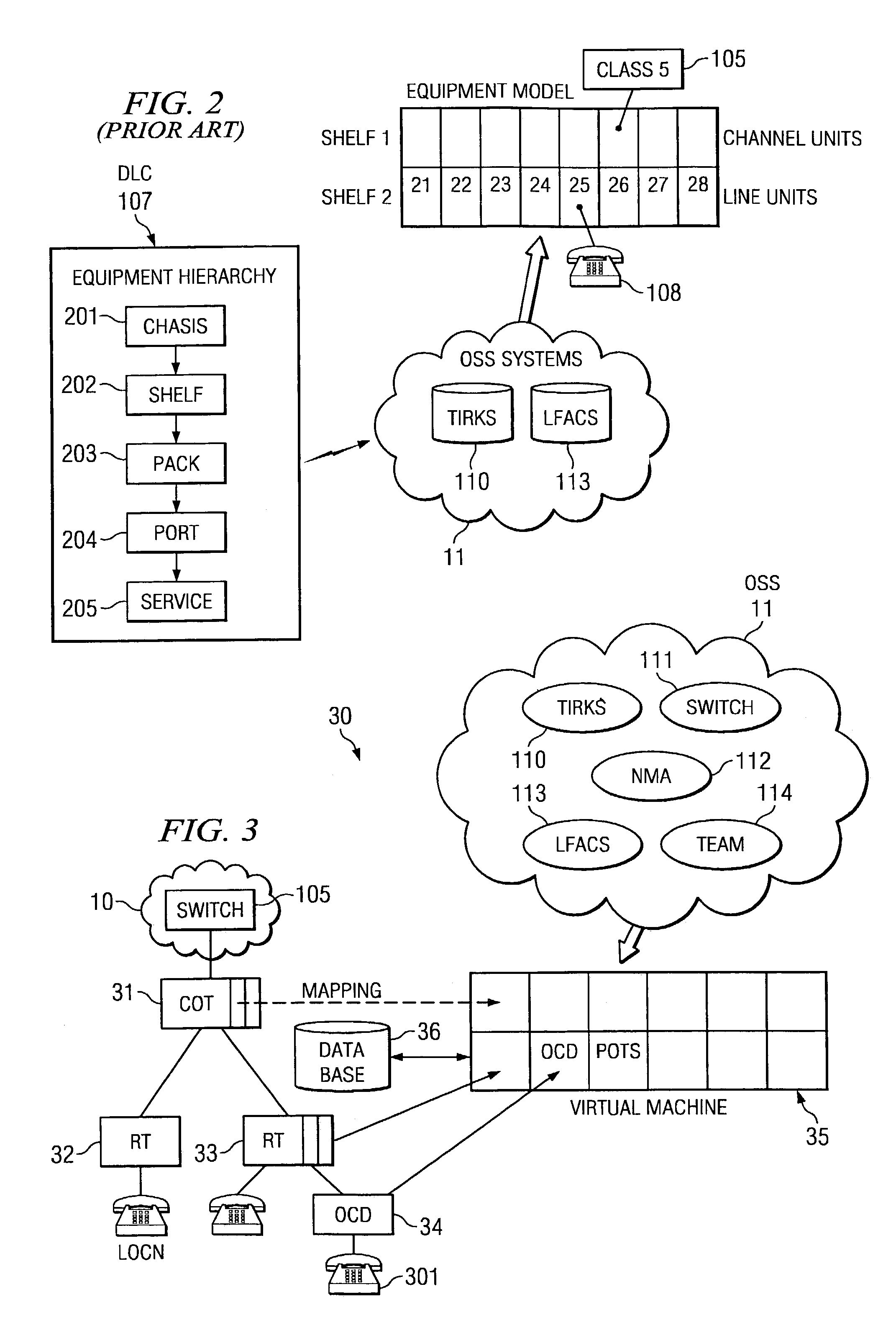
[0026]Network apparatus 10, which is a high level view of the current implementation of a telephone network, shows a set of switches 101, 102, 103, 104, 105 and 106. The class 5 switches, such as switches 104, 105, 106, implement local service and serve to connect subscribers, such as subscribers 108 and 108-1 together. An increasing trend starting in the early 80's has been to connect subscribers to remote line termination units called digital loop carriers, such as DLC 107. DLC 107 provides a direct interface for a variety of services to subscribers 108 and 108-1.

[0027]In operation, if subscriber 108 makes a call, its line is terminated by DLC 107 and the service for the call is...


PUM


Abstract

In one embodiment, a new device or service can be treated as an abstraction, allowing a model to be created which mimics operation of the device or service, but which does not physically exist. A communication system may then take physical assets that are distributed around a network, such as circuit packs with ports on them, and virtually plug them into a shelf that does not physically exist. A legacy system preferably continues to function as it always has and the abstraction mediates between the legacy operations support systems, the virtual machine and the physical reality. This then allows for the continued use of existing operation systems to manage new network architectures with services different from those originally contemplated by the legacy operations support systems.

Description

TECHNICAL FIELD[0001]This invention relates to communication network systems and more particularly to deploying new products and services in conjunction with traditional management provisioning systems.BACKGROUND OF THE INVENTION[0002]Large networks, such as communication networks, must be able to deploy and implement new services cost effectively. These systems are complex by their very nature and often rely on a set of operation systems that sit in the back office of a carrier and control the flow of provisioning and maintenance commands that ultimately actually manage the network plant, i.e. the physical equipment.[0003]The provisioning flow often starts with a customer request, as taken by a customer service representative, and moves through a service management layer, into a network management layer and ultimately to the physical equipment. This system allows a carrier to process and implement orders for service in an orderly manner. Because of the large volume of such orders, ...

Claims


Application Information

Patent Timeline
Patent Type & Authority Patents(United States)
IPC IPC(8): H04M1/24H04M3/22H04M3/08H04L12/24H04Q3/00
CPCH04Q3/0062H04L41/5054
Inventor WINTERBOTTOM, PHILIP
Owner TELEFON AB LM ERICSSON (PUBL)
Why Eureka
Try Eureka