Hydrogen and liquid fuel injection system

Inactive Publication Date: 2006-01-24
EMISSION CONTROLS CORP +1
View PDF19 Cites 40 Cited by
  • Summary
  • Abstract
  • Description
  • Claims
  • Application Information

AI Technical Summary

Benefits of technology

[0020]It is well established that the fuel system is the component of an internal combustion engine which often has the greatest impact on emissions, performance and cost. While almost all of the prior art has concentrated on the fuel systems which supply liquid fuel such as gasoline, it is well known that emissions can be reduced and performance increased by combusting a gaseous fuel such as hydrogen in an internal combustion engine. However, no infrastructure currently exists for the widespread distribution of

Problems solved by technology

However, no infrastructure currently exists for the wide

Method used


Image

  • Hydrogen and liquid fuel injection system
  • Hydrogen and liquid fuel injection system
  • Hydrogen and liquid fuel injection system

Examples


Embodiment Construction

[0041]Although the invention is described in terms of a preferred specific embodiment, it will be readily apparent to those skilled in this art that various modifications, rearrangements and substitutions can be made without departing from the spirit of the invention. The scope of the invention is defined by the claims appended hereto.

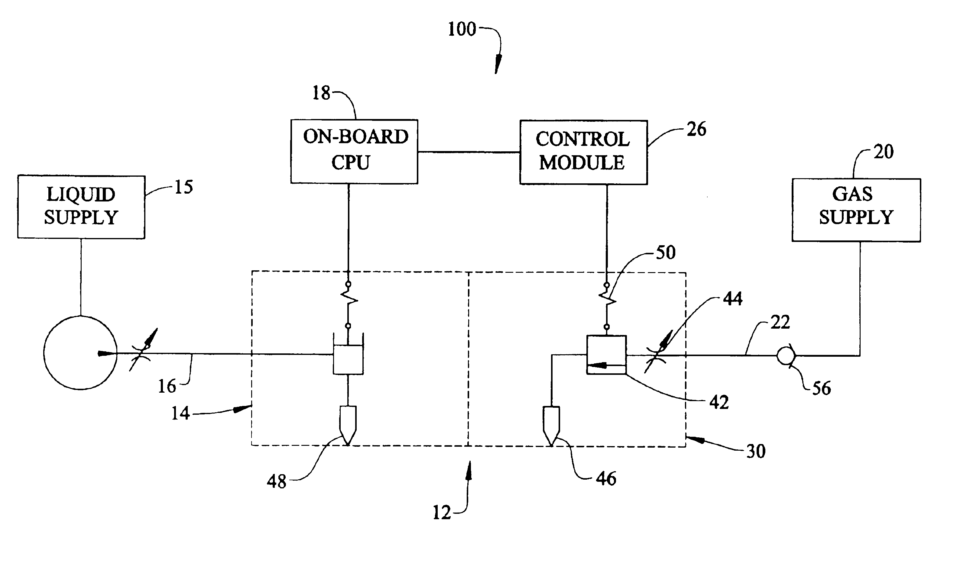
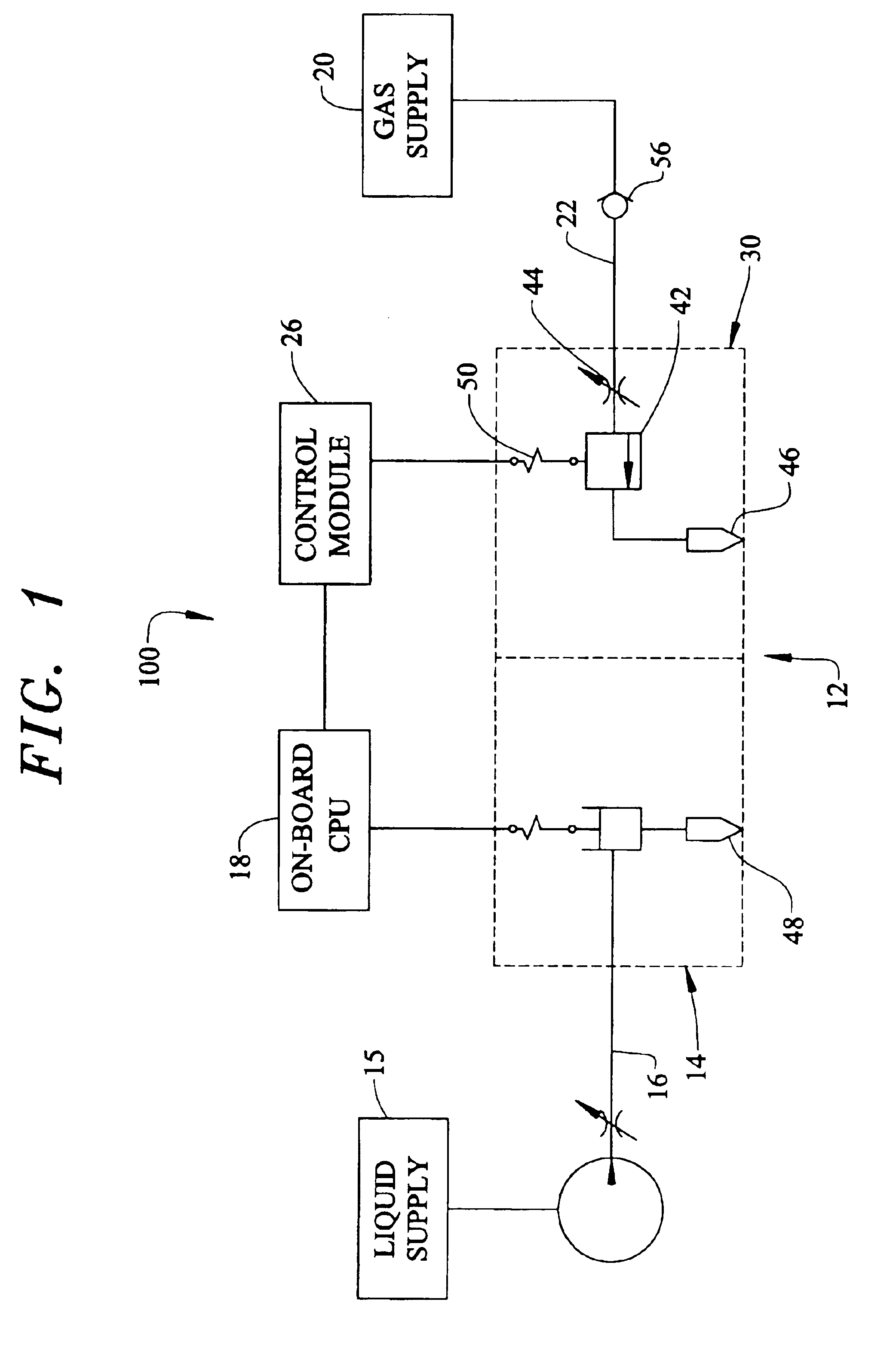
[0042]In order to permit operation of an internal combustion engine on hydrogen and / or a liquid fuel such as gasoline and the like, and due to the unsuitability of the prior art to be installed on pre-existing equipment without extensive modification to the equipment, the present invention utilizes an electrically controlled injection system 100 as set forth in FIG. 1.

[0043]Referring to FIG. 1, there is shown a schematic of the electrically controlled fuel injection system 100 of the present invention including electrically actuated unit injector 12 resulting in a flexible, efficient system capable of producing various combinations of discreet and blen...


PUM


Abstract

The present invention relates to a small adapter manifold that is constructed and arranged to fit into the standard fuel injector cavity for each cylinder of an automobile engine. The manifold includes a cavity for retaining the standard fuel injector and a liquid fuel passage, wherein the fuel injector can supply liquid fuel directly to the cylinder. The manifold also includes a separate hydrogen passage wherein a solenoid or servo valve regulates the flow of hydrogen entering each cylinder of the engine. A control module communicates with the on-board computer to allow the vehicle operator to choose a fuel. Once the fuel is chosen the computer utilizes the standard sensors to regulate the amount of hydrogen or gasoline supplied to the engine.

Description

FIELD OF THE INVENTION[0001]This invention relates to a fuel system for an internal combustion engine and more particularly to a device which cooperates with a standard fuel injector socket to control direct injection of hydrogen and / or liquid fuel to allow complete engine operation.BACKGROUND OF THE INVENTION[0002]A fuel system is the component of an internal combustion engine which often has the greatest impact on performance and cost. Accordingly, fuel systems for internal combustion engines have received a significant portion of the total engineering effort expended to date on the development of the internal combustion engine. For this reason, today's engine designer has an extraordinary array of choices and possible permutations of known fuel system concepts and features. Design effort typically involves extremely complex and subtle compromises among considerations such as cost, size, reliability, performance, ease of manufacture, and retrofit capability on existing engine desi...

Claims


Application Information

Patent Timeline
IPC IPC(8): F02M21/02F02D19/06
CPCF02D19/066F02M21/0281F02D19/0694F02M21/0254F02D19/0644Y02T10/32Y02T10/36F02D19/0671Y02T10/30
Inventor SHETLEY, MICHAEL
Owner EMISSION CONTROLS CORP
Why Eureka
Try Eureka