Flow regulating device

a flow regulating device and flow amount technology, applied in the direction of diaphragm valves, valve housings, instruments, etc., can solve the problems of severe limitation of the temperature range over which it is possible to perform accurate flow amount regulation, deviation, and damage to sealing structures, etc., to achieve accurate flow amount regulation and high reliability

Active Publication Date: 2006-01-24
SURPASS IND
View PDF2 Cites 23 Cited by
  • Summary
  • Abstract
  • Description
  • Claims
  • Application Information

AI Technical Summary

Benefits of technology

[0018]In order to achieve the above described objectives, the present invention proposes a flow adjustment device comprising a housing which is made from a resin material, and, within the housing, an intake port and an outlet port for fluid, a flow conduit which is disposed between these two ports, a valve seat which is formed in the flow conduit, and a valve element which controls the opening and closing of the valve seat; and wherein, within the housing, a shape preservation member which generally surrounds the environment of the flow conduit, and which is made from a material the amount of heat deformation of which is less than that of the material of the housing, thus restricting the amount of heat deformation of the housing, is provided.
[0019]According to this structure, heat deformation of the housing caused by variation of temperature of the fluid which is flowing through the flow conduit, or by change of temperature of the area in which the device is set up, or the like, is suppressed by the provision of the shape preservation member which is made from a material whose amount of heat deformation is lower than that of the material from which the housing is made, so that it is possible to preserve the shape of the flow conduit and of its surroundings. As a result, for example, it is possible to prevent leakage at the sealing surface, and it is possible to perform accurate regulation of the flow amount even if the temperature of the flowing fluid varies.
[0021]According to this structure, the flow conduit, the surroundings of the flow conduit, and the valve seat and the valve element which constitute portions of the flow conduit and so on are positioned so as to be sandwiched between the first plate member and the second plate member which are both made of metal and which are arranged with a fixed interval between them. Therefore, even if, as a result of change of temperature of the flowing fluid or the like, an attempt is made to deform the portions such as the flow conduit and its surroundings and so on which are sandwiched between the first plate member and the second plate member by heat, since the first plate member and the second plate member are not greatly deformed by this application of heat. Consequently, no great heat deformation occurs to these portions which are sandwiched between these plate members. In other words, change of the shape of the portions related to the flow conduit, such as for example the sealing surface and the valve seat and so on, is suppressed, and they are restricted to fixed positions within the housing. This matter is due to the fact that the first plate member and the second plate member are kept at a specific interval apart due to the dimensions of the spacer, and accordingly heat deformation between the first plate member and the second plate member comes to be completely restricted by this interval. That is, the shape of the flow conduit and of its surroundings are precisely maintained, and do not experience undue negative effect from change of the temperature of the flowing fluid or the like. Therefore, simply by using this low cost additional structure, it is possible to implement a flow regulating device which is capable of performing accurate flow amount regulation even for a flowing fluid whose temperature is varying. Furthermore, since this reinforcing structure is provided within the housing which is made from a resin material, accordingly it is possible to implement a flow regulating device with which accurate flow regulation can be obtained, even if the device is subjected to a shock from externally.
[0023]According to this structure, the possibility that, due to heat deformation or the like, the valve element insertion groove which governs the direction of operation of the valve element could become no longer able to govern the direction of operation of the valve element, is avoided. In other words, due to the provision of the valve element guide member which is made from a material which is different from the material of the housing in the valve element insertion groove which is formed in the housing which is made from resin, the construction of the above described valve element insertion groove comes to be reinforced with respect to the influence of the application of heat, and deformation due to, for example, variation of the temperature of the flowing fluid, variation of the temperature of the external environment, or deformation of the valve element by friction, or heating of the valve element generated by slight sliding action of the valve element, is avoided, and the operational direction of the valve element and the smooth operation of the valve element are always maintained. Due to this unstable operation of the valve element, such as tilting, juddering, or severe vibration thereof, can be eliminated in any temperature region, and the valve element comes to shift smoothly and precisely along its predetermined axial line. As a result, during operation of the valve element, an opening amount of the valve seat comes to be obtained which corresponds accurately and moreover stably to the regulation value for the flow amount. Therefore, it is possible to enhance the accuracy of regulation of the flow amount through the valve seat, even if the device is utilized for controlling the flow of a fluid whose temperature is varying, or in an external environment whose temperature is varying, or the like. It should be understood that, as the material for the valve element guide member, it is desirable for it to be made from a resin which has allows the valve element to slide smoothly and which has excellent corrosion resistance, and a resin will be acceptable which is one which is less deformed by heat than is the material of which the housing is made.
[0025]According to this structure, even in circumstances such as ones in which a negative influence upon the regulation of the flow amount is being exerted, an appropriate flow amount of liquid comes to be allowed to flow through the flow conduit whose heat deformation, along with that of its surroundings, is regulated by the provision of the shape preservation member. Moreover, the opening amount of the valve seat is stabilized by the guidance of the operation of the valve element which is provided by the valve element guide member which is made from a material the amount of heat deformation of which is less than that of the material of the housing. Therefore, it is possible to flow as appropriate flow amount past the valve seat, in correspondence to any desired regulation value for this flow amount. Consequently, it is possible to implement a flow regulating device which can perform accurate flow amount regulation even in circumstances in which it is suffering variation of temperature, and moreover whose reliability is high.

Problems solved by technology

As a result, deviation can arise in such flow amount regulation, due to variation over a short time period of the temperature of the fluid whose flow amount is to be regulated, or due to variation of the temperature of the external environment.
This can cause the result that the temperature range over which it is possible to perform accurate flow amount regulation may be severely limited.
However, since this type of resin material has a rather great amount of heat deformation as compared to metallic materials of the flow regulating device, it can sometimes happen that, due to deviation occurring at the sealing surface of the flow conduit, the sealing structure may be destroyed.

Method used


Image

  • Flow regulating device
  • Flow regulating device
  • Flow regulating device

Examples


first preferred embodiment

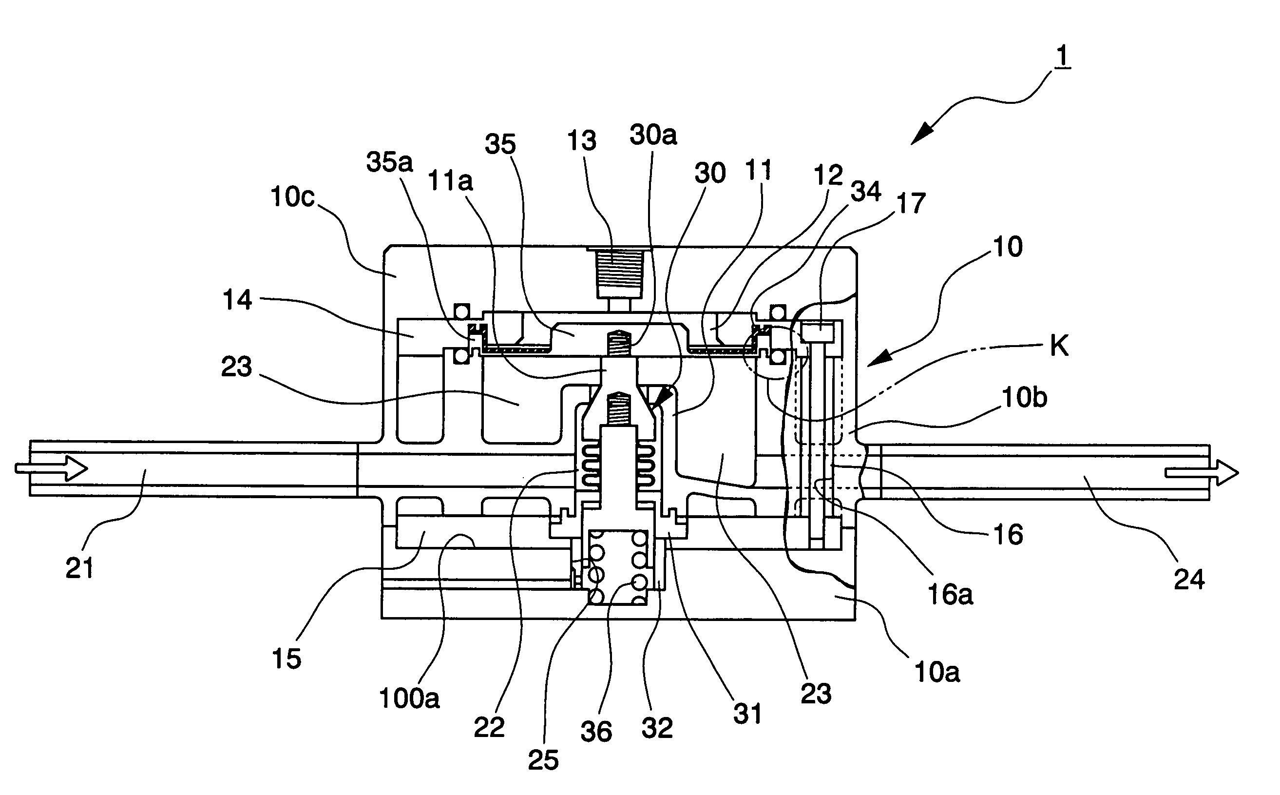
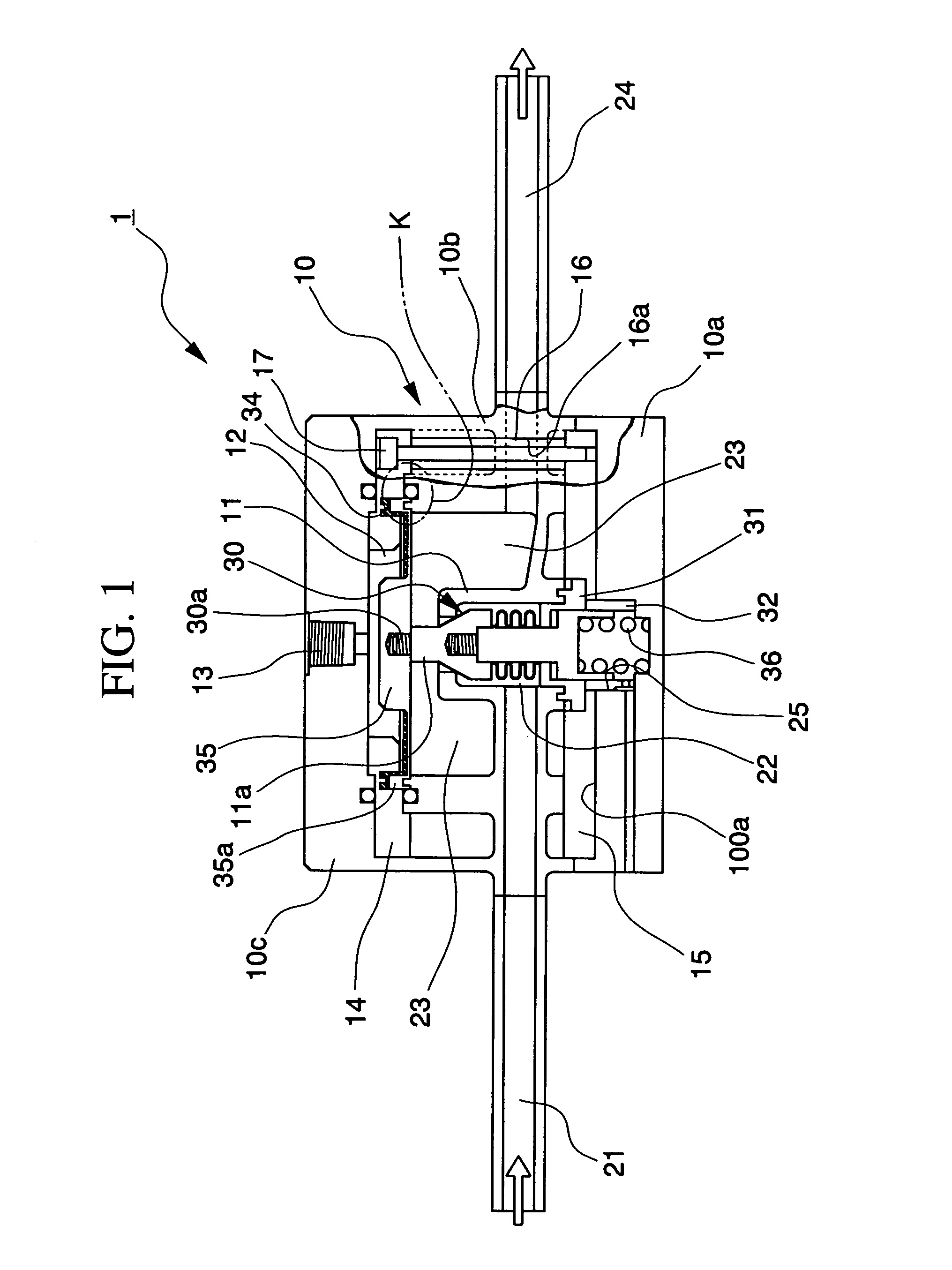
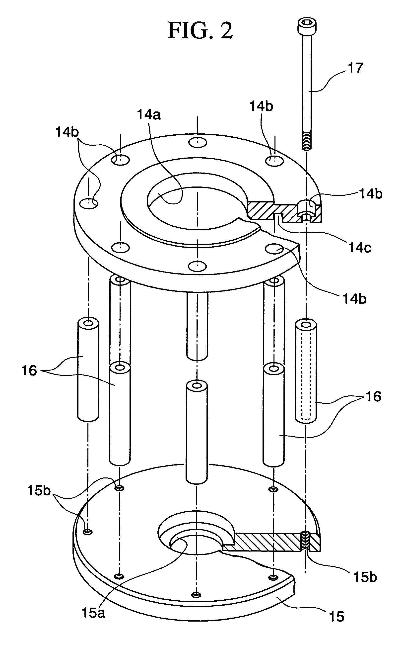
[0031]FIG. 1 is a sectional figure for explanation of the internal structure of the flow regulating device according to the first preferred embodiment of the present invention. And FIG. 2 is a perspective view for explanation of the structure of a shape preservation member which is provided within its housing. In this embodiment the rated flow amount which is supplied from an outlet port 24 of the flow regulating device 1 which is explained here is from 4 to 35 liters / minute. In addition, in the explanation of the basic construction for regulating the rated flow amount within the above range, the explanation of portions thereof will be curtailed herein, since they are almost the same as the structure of the flow regulating device 1 which has been explained above with respect to FIG. 4, so that the detailed explanation will focus upon the structure of the portions which are related to the present invention.

[0032]A housing 10 which gives this flow regulating device 1 its external appe...

second preferred embodiment

[0052]Next, a flow regulating device 1′ according to a second preferred embodiment of the present invention will be explained. It should be understood that this flow regulating device 1′ according to the second preferred embodiment of the present invention differs from the above described flow regulating device 1 according to the first preferred embodiment of the present invention by the addition of a supplemental structure for hyper-fine operation of the valve element 30, the structure and operation related to this feature will be described in detail, while, as far as the other structures of this device 1′ are concerned, the explanation thereof will be partially curtailed, since they are the same as in the case of the first preferred embodiment described above.

[0053]The flow regulating device 1 of this second preferred embodiment of the present invention which is shown is one which comprises a piston 40 which somewhat presses downwards the valve element 30, via a diaphragm 35, in o...


PUM


Abstract

The flow regulating device has a shape preservation member which surrounding the environment of a flow conduit and restricts the amount of heat deformation of a housing in the housing. The shape preservation member is made from a material whose amount of heat deformation is lower than that of the housing. Furthermore, the shape preservation member includes a first metal plate member positioned on one side of the flow conduit, a second metal plate member positioned on the other side of the flow conduit, a spacer which maintains a constant interval between the first and second plate members, and bolts which fix together the first and second plate members via the spacer. In this flow regulating device, while maintaining excellent chemical resistance by making a housing from resin, accurate flow amount regulation over a wide temperature range can be performed.

Description

BACKGROUND OF THE INVENTION[0001]1. Field of the Invention[0002]The present invention is related to a flow regulating device which controls the flow amount of a liquid chemical or pure water or the like, and is related to Patent Application No. 2002-328116, filed Nov. 12, 2002, the content of which is incorporated herein by reference.[0003]2. Description of Related Art[0004]FIG. 4 is a sectional figure which shows an example of the construction of a prior art type flow regulating device. This type of flow regulating device 1 is one which is used in a supply line for the flow of a fluid, when mixing together a plurality of different liquid chemicals, or when accurately regulating the flow amount of pure water or the like which is to be used for a manufacturing process for a product. Furthermore, a flow regulating device 1 which is used for this sort of application is also sometimes generally termed a“regulator”.[0005]The structure of this flow regulating device 1 will now be explaine...

Claims


Application Information

Patent Timeline
Patent Type & Authority Patents(United States)
IPC IPC(8): F16K17/30F16K7/17F16K27/02F16K31/122F16K31/365G05D7/01
CPCF16K7/17G05D7/0106F16K31/365F16K31/1221Y10T137/7737
Inventor IGARASHI, HIROKI
Owner SURPASS IND
Why Eureka
Try Eureka