
Rocker lever assembly

a technology of lever assembly and rocker lever, which is applied in the direction of mechanical control devices, instruments, manual control with single controlling member, etc., can solve the problems of increasing package, storage and transportation costs, and achieve the effects of enhancing sensitivity, reducing volume of the rocker lever assembly, and enhancing the lifetime of the operation devi

Inactive Publication Date: 2006-01-24
TAIWAN PWL CORP
View PDF9 Cites 27 Cited by
  • Summary
  • Abstract
  • Description
  • Claims
  • Application Information

AI Technical Summary

Benefits of technology

[0014]The primary objective of the present invention is to provide a rocker lever assembly, wherein the spring has a first end mounted on the mounting seat of the urging race and a second end mounted on the flange of the base, so that the volume of the rocker lever assembly is reduced largely.
[0015]Another objective of the present invention is to provide a rocker lever assembly, wherein the contact slide is displaced on the resistance plate of the casing by guidance of the drive member, thereby greatly enhancing the sensitivity of each of the two sensing variable resistors.
[0016]A further objective of the present invention is to provide a rocker lever assembly, wherein the first pivot seat and the second pivot seat are made of wear-resistant material, thereby enhancing the lifetime of the operation device.
[0017]A further objective of the present invention is to provide a rocker lever assembly, wherein the switch device is hidden in the housing, thereby reducing the volume of the rocker lever assembly.

Problems solved by technology

However, the switch device mounted on the outside of the housing, so that the conventional rocker lever has a larger volume, thereby increasing costs in package, storage and transportation.

Method used


Image

  • Rocker lever assembly
  • Rocker lever assembly
  • Rocker lever assembly

Examples


Embodiment Construction

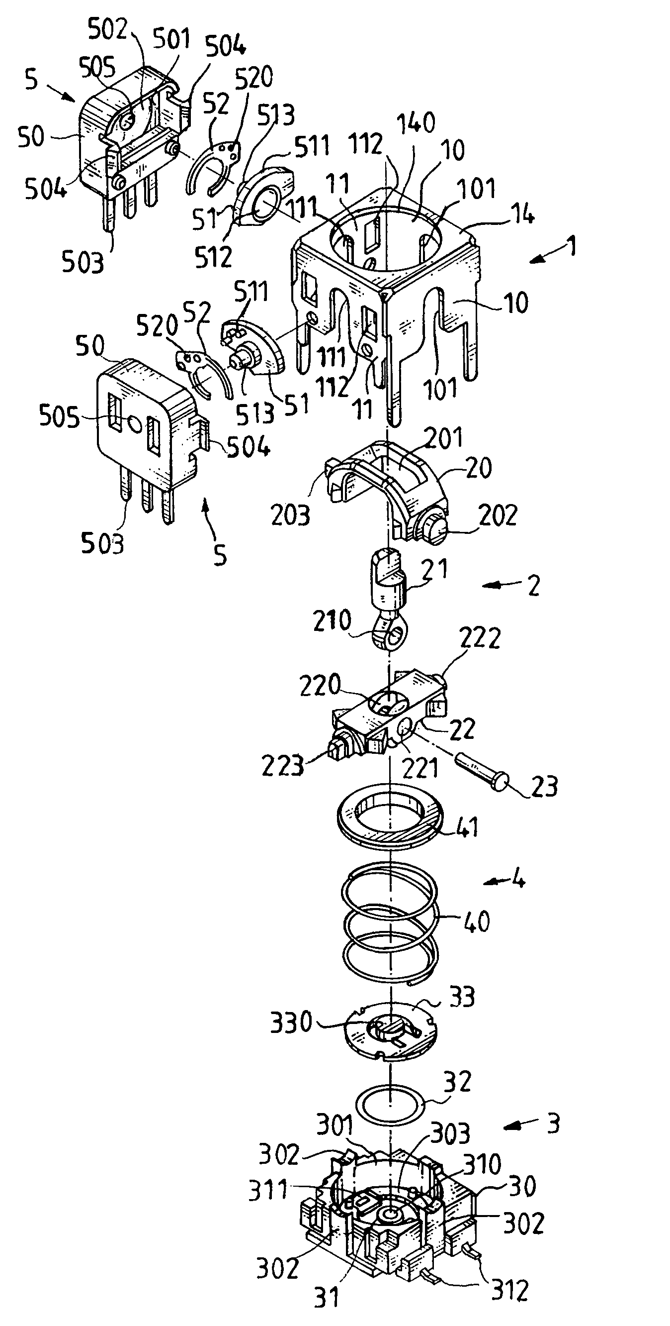
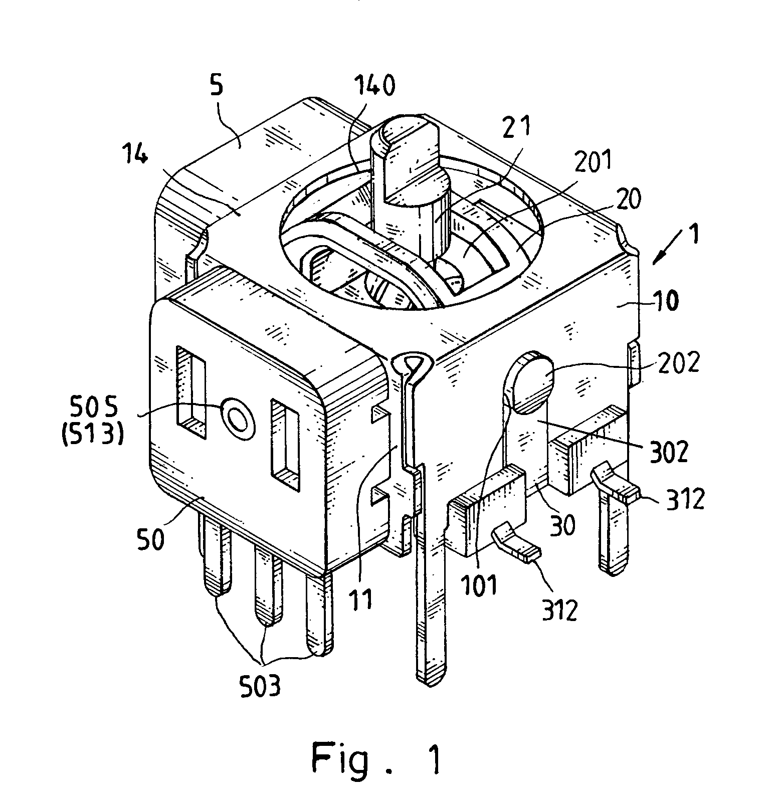
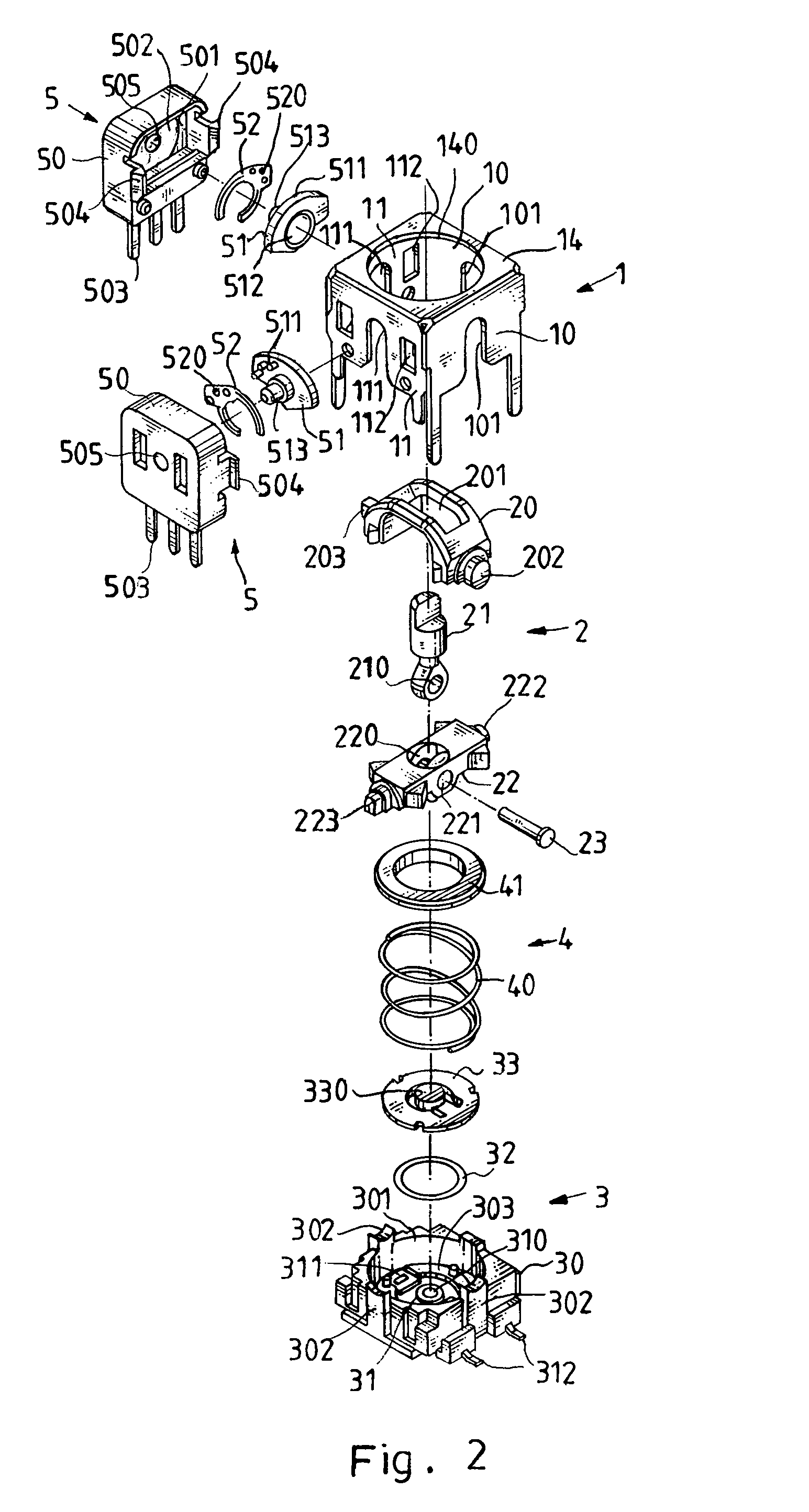
[0022]Referring to FIGS. 1–3, a rocker lever assembly in accordance with the preferred embodiment of the present invention comprises a housing 1, an operation device 2, a switch device 3, a restoring device 4, and two sensing variable resistors 5.

[0023]The housing 1 is hollow and includes a top plate 14, two adjacent first side plates 10, and two adjacent second side plates 11.

[0024]The top plate 14 of the housing 1 is formed with an operation hole 140.

[0025]Each of the two first side plates 10 of the housing 1 is bendable and is formed with an opening 101 facing downward.

[0026]Each of the two second side plates 11 of the housing 1 is bendable and is formed with an opening 111 facing downward. Each of the two second side plates 11 of the housing 1 is formed with two spaced locking holes 112.

[0027]The operation device 2 is mounted in the housing 1 and includes a first pivot seat 20, a second pivot seat 22, and a control lever 21.

[0028]The first pivot seat 20 of the operation device 2...


PUM


Abstract

A rocker lever assembly includes a housing, an operation device, a switch device, a restoring device, and two sensing variable resistors. The operation device includes a first pivot seat, a second pivot seat, and a control lever. The switch device includes a base, a contact terminal, a contact plate, and a cover plate. The control lever is depressed to cause the under surface of the second pivot seat to depress the cover plate. Thus, the switch device is hidden in the housing, thereby reducing the volume of the rocker lever assembly. In addition, the contact slide is moved on the resistance plate of the casing by guidance of the drive member, thereby greatly enhancing the sensitivity of each of the two sensing variable resistors.

Description

BACKGROUND OF THE INVENTION[0001]1. Field of the Invention[0002]The present invention relates to a rocker lever assembly, and more particularly to a rocker lever assembly available for controlling the navigation direction or data change of a personal digital product, such as the PDA, video game, cell phone, portable computer or the like.[0003]2. Description of the Related Art[0004]A conventional rocker lever comprises a housing, an operation device mounted in the housing, a switch device mounted on an outside of the housing, a restoring device mounted in the housing, and two variable resistors mounted on an outside of the housing. The operation device includes a first pivot seat pivotable in a longitudinal direction, a second pivot seat pivotable in a transverse direction perpendicular to that of the first pivot seat, and a control lever movable in the longitudinal direction and the transverse direction to pivot the first pivot seat and the second pivot seat in the longitudinal dire...

Claims


Application Information

Patent Timeline
IPC IPC(8): H01H25/04
CPCG05G9/047H01C10/36H01H25/00H01C10/345G05G2009/04748G05G2009/04777H01H25/04H01H25/008
Inventor LEE, MEI-HSIU
Owner TAIWAN PWL CORP
Learn More