
LED driving device

a driving device and led technology, applied in the direction of identification means, instruments, process and machine control, etc., can solve the problems of shortening the life of leds, lowering the power factor, and requiring tuning of capacitors and inductor

Active Publication Date: 2006-01-24
SIGNIFY HLDG BV
View PDF10 Cites 239 Cited by
  • Summary
  • Abstract
  • Description
  • Claims
  • Application Information

AI Technical Summary

Benefits of technology

[0015]For overcoming said defects described above, an object of the present invention is to provide an LED driving device in which the LEDs can be driven by the positive part of power source directly.
[0016]Another object of the present invention is to provide a LED driving device in which the power factor can be improved.

Problems solved by technology

Another disadvantage is that the capacitor and inductor have to be tuned with the frequency of AC voltage source.
Although this patent can avoid light intensity from dropping down without increasing the power consumption, but driving LEDs with increased current will shorten the life of LEDs.
The disadvantages for the existence of capacitor are lowering the power factor and the capacitor has to be changed with the frequency of power source.
Besides, the life and stability of capacitor is affected by temperature very heavily so that it makes the driving device unstable.

Method used


Image

  • LED driving device
  • LED driving device
  • LED driving device

Examples


Embodiment Construction

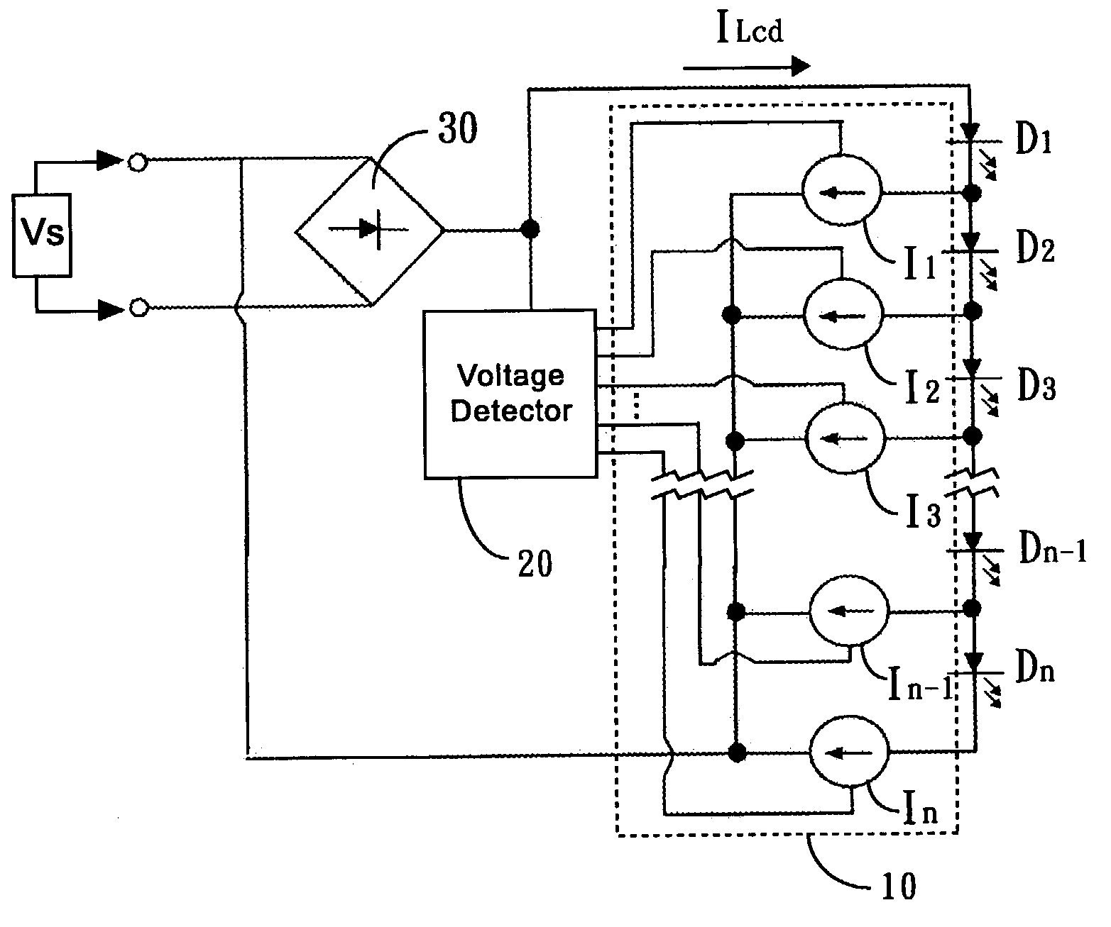
[0033]FIG. 5A is a circuit diagram of the first embodiment of the present invention. It comprises a LED string, a voltage detecting circuit 20 and a current switching circuit 10. The power source Vs can be any kind of input voltage source. Said voltage detecting circuit 20 is used for detecting the voltage level of the power source Vs and said current switching circuit 10 including grounded current controlling unit I1, I2, I3, . . . , I(n−1), and In.

[0034]Said LED string connected in parallel across the power source Vs is composed of series connected LED sets D1, D2, D3, . . . , Dn−1, and Dn. Each of said LED sets is composed of a LED or at least two LEDs in any electric configuration.

[0035]The current controlling unit I1, I2, I3, . . . , I(n−1), In is coupled to one of the LED sets. The voltage detecting circuit 20 detects the voltage level of power source and sends a signal to said current switching circuit 10 and said current switching circuit 10 is automatically activated to ena...


PUM


Abstract

A LED driving device includes a plurality of LEDs, a voltage detecting circuit, and a current switching circuit. When the voltage detecting circuit detects the different voltage level of power source without coupling to a filtering capacitor, it sends a signal to the current switching circuit and then the current switching circuit is automatically activated to electrically rearrange the configuration of LEDs with a predetermined current value by lighting the greatest number of LEDs that improving the power factor and efficiency.

Description

BACKGROUND OF THE INVENTION[0001]1. Field of the Invention[0002]The present invention relates to a driving device, and more particularly it pertains to a LED driving device capable of improving the power factor and efficiency.[0003]2. Description of the Related Art[0004]Diode, a semi-conductor element, works like a switch, has played an important role in electronic system.[0005]There are many kinds of diode around our life. One kind of diode can be lighting when being energized. This kind of diode we call it Light Emitting Diode (LED).[0006]The application of LED is quite wide. High bright LED is widely used for traffic light, vehicle indicating light, and braking light. Full-color LED display, composed of red LED, green LED, and blue LED, is also used for stadium and street advertisement, such as the larg LED display at outside of Nasdaq marketing center in Times Square, New York city. The 20-foot high screen, composed of 19,000,000 high bright LEDs, is the largest one in the world...

Claims


Application Information

Patent Timeline
Patent Type & Authority Patents(United States)
IPC IPC(8): G09G3/32H05B44/00
CPCH05B33/083H05B33/0809H05B45/48
Inventor CHIANG, JOHNSON
Owner SIGNIFY HLDG BV
Learn More