Two-group zoom lens
a two-group, zoom lens technology, applied in the field of monitor cameras, can solve the problem of out of focus of near-infrared images captured at night, and achieve the effects of comparatively bright imaging, low f-number, and favorable correction of chromatic aberration
- Summary
- Abstract
- Description
- Claims
- Application Information
AI Technical Summary
Benefits of technology
Problems solved by technology
Method used
Image

Examples
embodiment 1-1
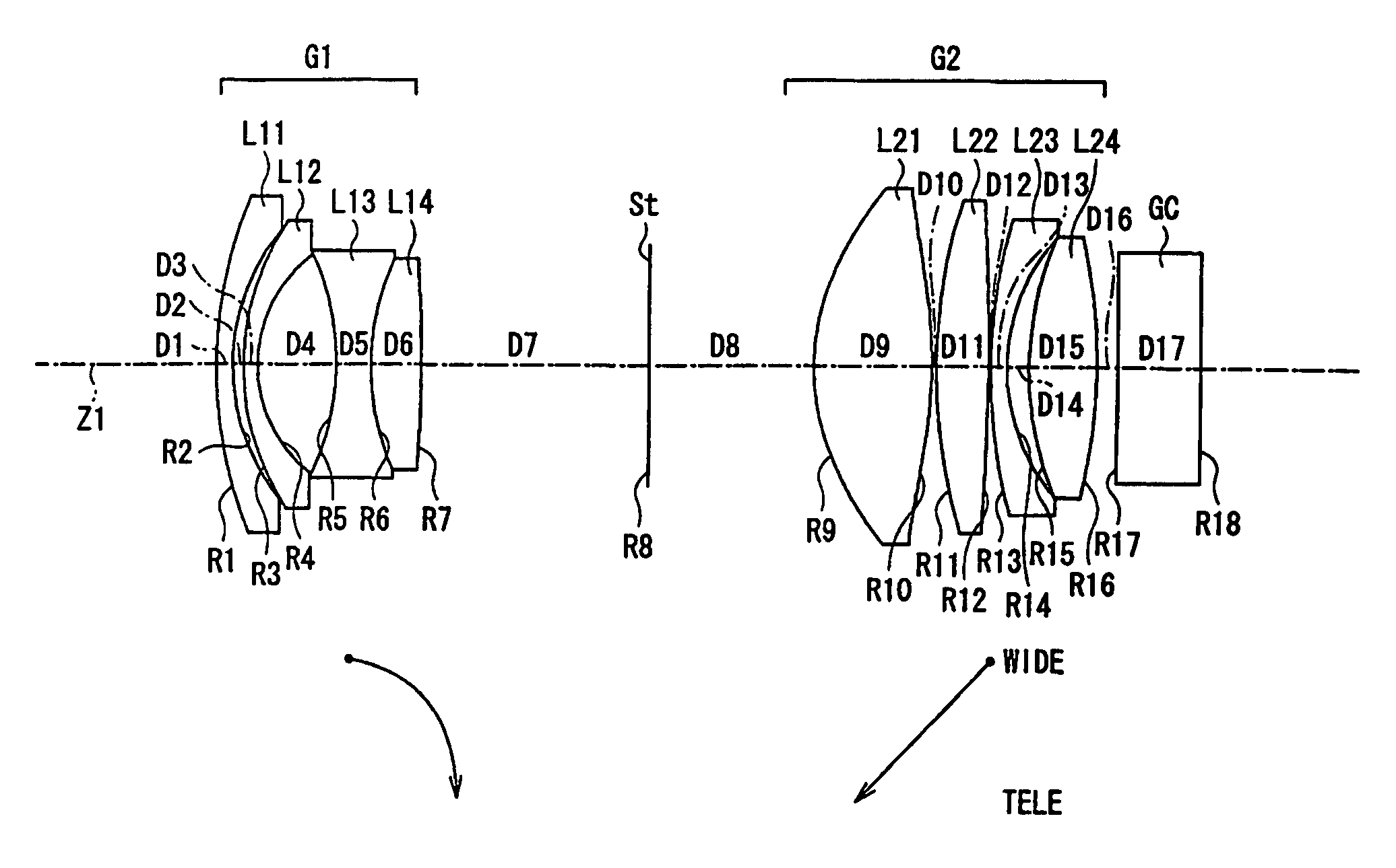
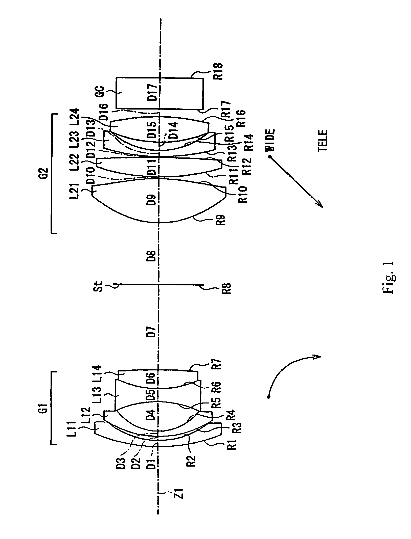
[0055]FIG. 1 shows a cross-sectional view of Embodiment 1-1 of the zoom lens of the present invention at the wide-angle end. In this zoom lens, spherical aberration that occurs with large a low f-number lens is easily corrected by the first lens element L21 of the second lens group G2 including an aspheric surface, in particular by both lens surfaces being aspheric. Because it is the first lens element L21 of the second lens group G2 that includes an aspheric surface, it is easier to keep sensitivity to eccentricity low.
[0056]Embodiment 1-1 preferably satisfies the following condition concerning the Abbe number at the d-line (587.6 nm) of the first lens element L21 the second lens group G2:
νdL21>60 Condition (5-1)
where
[0057]νdL21 is the Abbe number at the d-line (587.6 nm) of the first lens element L21 of the second lens group G2.
[0058]If an aspheric lens element L21 that satisfies Condition (5-1) is properly selected, axial chromatic aberration over the visible to near-infrared ra...
embodiment 1-2
[0069]FIG. 4 shows a cross-sectional view of Embodiment 1-2 of the zoom lens of the present invention at the wide-angle end. Embodiment 1-2 is very similar to Embodiment 1-1 and therefore only the differences between Embodiment 1-2 and Embodiment 1-1 will be explained. Embodiment 1-2 differs from Embodiment 1-1 in its lens element configuration such as different radii of curvature of the lens surfaces, different eccentricities and aspheric coefficients of the aspheric lens surfaces, some different optical element surface spacings, some different refractive indexes, and some different Abbe numbers of the optical materials of the lens elements.
[0070]Table 5 below lists the surface number #, in order from the object side, the radius of curvature R (in mm) of each surface near the optical axis, the on-axis surface spacing D (in mm), as well as the refractive index Nd and the Abbe number νd (both at the d-line of 587.6 nm) of each optical element for Embodiment 1-2.
[0071]
TABLE 5#RDNdνd 1...
embodiment 2-1
[0080]FIG. 7 shows a cross-sectional view of Embodiment 2-1 of the zoom lens of the present invention at the wide-angle end. Embodiment 2-1 is very similar to Embodiment 1-1 and therefore only the differences between Embodiment 2-1 and Embodiment 1-1 will be explained. In this zoom lens; spherical aberration that occurs with low f-numbers is easily corrected by the second lens element L22 of the second lens group G2 including an aspheric surface, in particular by both lens surfaces being aspheric, rather than both lens surfaces of the first lens element L21 of the second lens group G2 being aspheric as in Embodiment 1-1 (and Embodiment 1-2). Additionally, the aspheric shape of the image-side surface of the second lens element L22 of the second lens group G2 is such that the curvature C is equal to zero on the optical axis. The curvature C is defined as equal to one divided by the radius of curvature R so that the radius of curvature R is equal to infinity on the optical axis. This d...
PUM
 Abstract
Description
Claims
Application Information
PatSnap Eureka turns technology decisions into work you can execute. Powered by our Innovation Knowledge Graph, it runs expert workflows across engineering, life sciences, materials and intellectual property. Get your review-ready output in minutes.


