Zoom lens system

a zoom lens and lens body technology, applied in the field of zoom lens system, can solve the problems of difficult aberration correction of field curvature and axial chromatic aberration, insufficient optical quality of digital slr camera with high pixelization, and reduce axial chromatic aberration. , to achieve the effect of superior optical quality

Active Publication Date: 2018-10-09
RICOH IMAGING COMPANY
View PDF19 Cites 0 Cited by
  • Summary
  • Abstract
  • Description
  • Claims
  • Application Information

AI Technical Summary

Benefits of technology

[0009]The present invention has been devised in view of the above mentioned problems, and provides a zoom lens system that achieves a superior optical quality by favorably correcting various aberrations such as chromatic aberration, etc.
[0027]According to the present invention, a zoom lens system can be provided that achieves a superior optical quality by favorably correcting various aberrations such as chromatic aberration, etc.

Problems solved by technology

In regard to chromatic aberration, although in recent years it has become possible to correct lateral chromatic aberration to a certain extent by performing image processing on the photographed image using software in-built into the camera or by using software installed in a computer, in order to achieve an optical quality having a higher sense of resolution, it has been a technical problem to sufficiently reduce axial chromatic aberration.
Furthermore, field curvature and axial chromatic aberration are difficult aberrations to correct via image processing in an after-process.
However, in Patent Literature 1 through 3 (zoom lens systems), since correction of various aberrations such as chromatic aberration is insufficient, the optical quality thereof is not enough for digital SLR cameras that have high pixelization.

Method used


Image

  • Zoom lens system
  • Zoom lens system
  • Zoom lens system

Examples


numerical embodiment 1

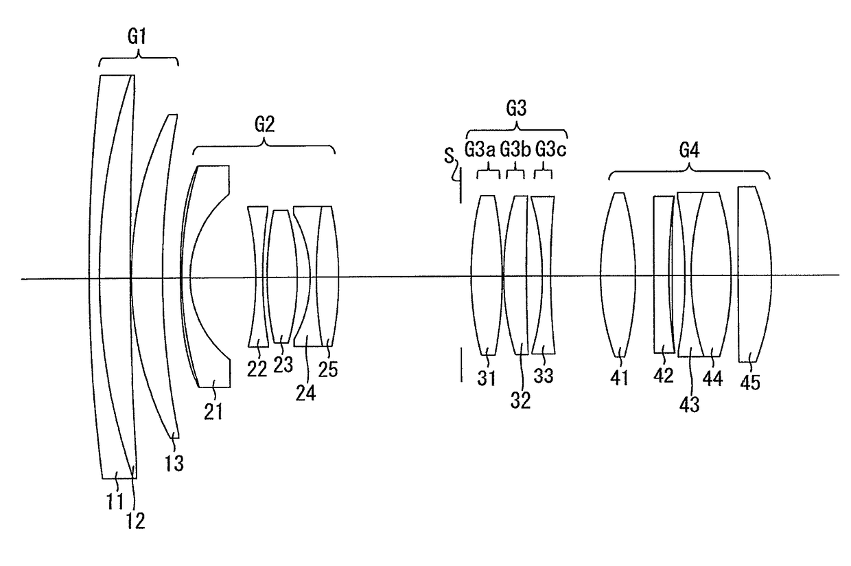
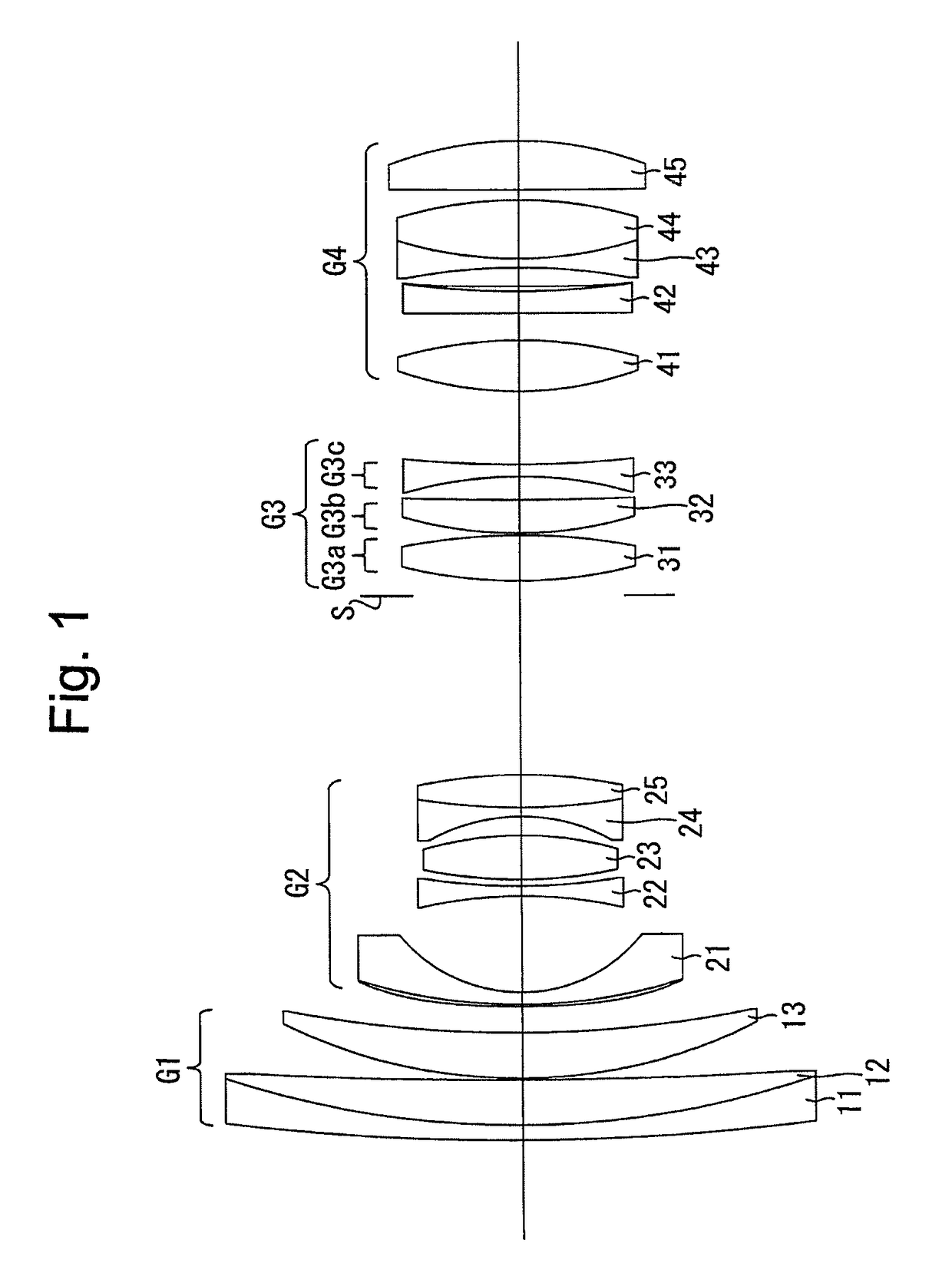
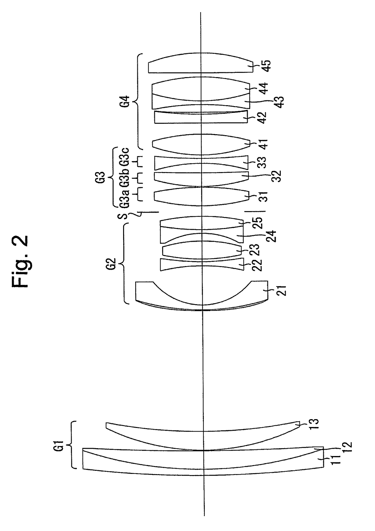
[0105]FIGS. 1 through 4D and Tables 1 through 4 disclose a first numerical embodiment of the zoom lens system according to the present invention. FIG. 1 shows a lens arrangement of the first numerical embodiment of the zoom lens system when focused on an object at infinity at the short focal length extremity. FIGS. 3A, 3B, 3C and 3D show various aberrations that occurred in the zoom lens system of FIG. 1. FIG. 2 shows a lens arrangement of the first numerical embodiment of the zoom lens system when focused on an object at infinity at the long focal length extremity. FIGS. 4A, 4B, 4C and 4D show various aberrations that occurred in the zoom lens system of FIG. 2. Table 1 indicates the surface data, Table 2 indicates various lens system data, Table 3 indicates aspherical surface data, and Table 4 indicates lens-group data.

[0106]The zoom lens system of the first numerical embodiment is configured of a positive first lens group G1, a negative second lens group G2, a positive third lens ...

numerical embodiment 2

[0115]FIGS. 5 through 8D and Tables 5 through 8 disclose a second numerical embodiment of the zoom lens system according to the present invention. FIG. 5 shows a lens arrangement of the second numerical embodiment of the zoom lens system when focused on an object at infinity at the short focal length extremity. FIGS. 7A, 7B, 7C and 7D show various aberrations that occurred in the zoom lens system of FIG. 5. FIG. 6 shows a lens arrangement of the second numerical embodiment of the zoom lens system when focused on an object at infinity at the long focal length extremity. FIGS. 8A, 8B, 8C and 8D show various aberrations that occurred in the zoom lens system of FIG. 6. Table 5 indicates the surface data, Table 6 indicates various lens system data, Table 7 indicates aspherical surface data, and Table 8 indicates lens-group data.

[0116]The lens arrangement of the zoom lens system of the second numerical embodiment is the same as that of the first numerical embodiment, except for the follow...

numerical embodiment 3

[0123]FIGS. 9 through 12D and Tables 9 through 12 disclose a third numerical embodiment of the zoom lens system according to the present invention. FIG. 9 shows a lens arrangement of the third numerical embodiment of the zoom lens system when focused on an object at infinity at the short focal length extremity. FIGS. 11A, 11B, 11C and 11D show various aberrations that occurred in the zoom lens system of FIG. 9. FIG. 10 shows a lens arrangement of the third numerical embodiment of the zoom lens system when focused on an object at infinity at the long focal length extremity. FIGS. 12A, 12B, 12C and 12D show various aberrations that occurred in the zoom lens system of FIG. 10. Table 9 indicates the surface data, Table 10 indicates various lens system data, Table 11 indicates aspherical surface data, and Table 12 indicates lens-group data.

[0124]The lens arrangement of the zoom lens system of the third numerical embodiment is the same as that of the second numerical embodiment.

[0125]

TABL...


PUM


Abstract

A zoom lens system includes a positive first lens group, a negative second lens group, a positive third lens group and a positive fourth lens group, in that order from the object side, wherein distances between adjacent lens groups thereof change during zooming. The third lens group includes a positive first sub-lens group, a positive second sub-lens group and a negative third sub-lens group. The third sub-lens group consists of a single negative lens element. The following conditions (1) and (2) are satisfied:6.0<f1Gp / fw<9.0  (1), and1.3<f3Gp / f4Gp<2.0  (2),wherein fw designates the focal length of the entire zoom lens system at the short focal length extremity, f1Gp, f3Gp and f4Gp designate the focal lengths of the first, third and fourth lens groups, respectively.

Description

BACKGROUND OF THE INVENTION1. Field of the Invention[0001]The present invention relates to a zoom lens system, and relates to, e.g., a zoom lens system that is suitable for installation in an imaging apparatus such as a digital camera, etc.2. Description of Related Art[0002]Various types of large-aperture standard zoom lens systems, which include a wide-angle capability in particular, for use in SLR (Single-Lens Reflex) digital cameras are known in the related art. Out of such zoom lens systems, typically a zoom lens system configured of a positive lens group, a negative lens group, a positive lens group and a positive lens group (four lens groups) is used as a large-aperture standard zoom lens system, in which the zoom ratio is approximately 3:1 (Patent Literature 1 through 3).[0003]On the other hand, in a digital SLR camera, due to high pixelization of the image sensor thereof, the sense of resolution is high over the entire focal length range, so that an optical system having a h...

Claims


Application Information

Patent Timeline
Patent Type & Authority Patents(United States)
IPC IPC(8): G02B15/14G02B15/177G02B15/167
CPCG02B15/177G02B15/167G02B15/144113
Inventor NOMURA, YOICHI
Owner RICOH IMAGING COMPANY
Why Eureka
Try Eureka