Zoom lens system

a zoom lens and zoom lens technology, applied in the field of zoom lens systems, can solve the problems of insufficient correction of various aberrations over the zooming range from the short focal length extremity to the long focal length extremity, large amount of aberrations (especially spherical aberrations), and the effect of superior optical quality

Active Publication Date: 2019-07-02
RICOH IMAGING COMPANY
View PDF24 Cites 0 Cited by
  • Summary
  • Abstract
  • Description
  • Claims
  • Application Information

AI Technical Summary

Benefits of technology

[0007]The present invention has been devised in view of the above mentioned problems, and provides a zoom lens system that achieves a superior optical quality by favorably correcting various aberrations over the entire zooming range.
[0033]According to the present invention, a zoom lens system can be provided that achieves a superior optical quality by favorably correcting various aberrations over the entire zooming range.

Problems solved by technology

However, generally, a large amount of aberrations (especially spherical aberration) occur in a zoom lens system that includes a telephoto range.
However, in the zoom lens systems disclosed in Patent Literature 1 and 2, the correction of various aberrations over the zooming range from the short focal length extremity to the long focal length extremity is insufficient, and the optical quality tends to deteriorate.

Method used


Image

  • Zoom lens system
  • Zoom lens system
  • Zoom lens system

Examples


embodiment 1

[Numerical Embodiment 1]

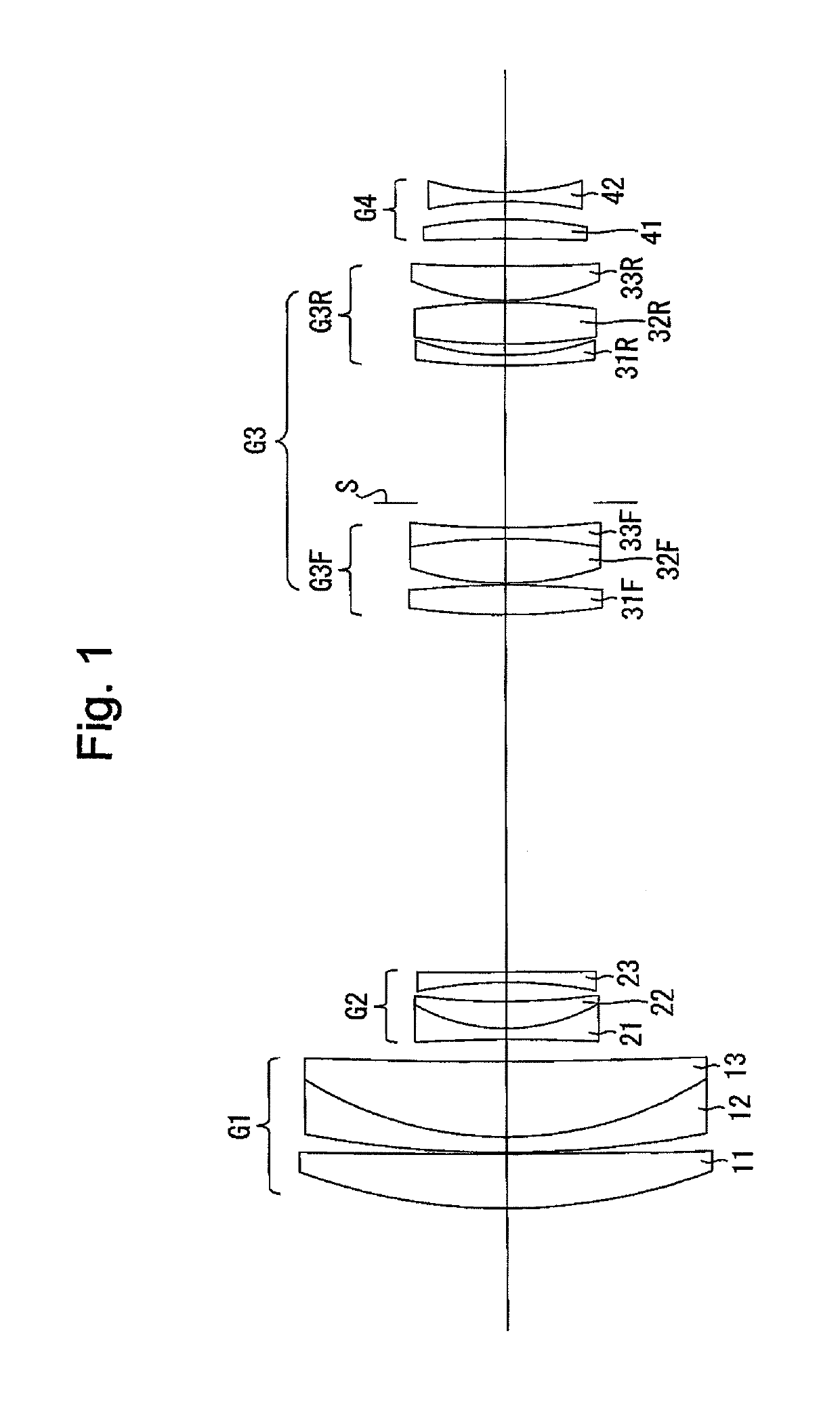
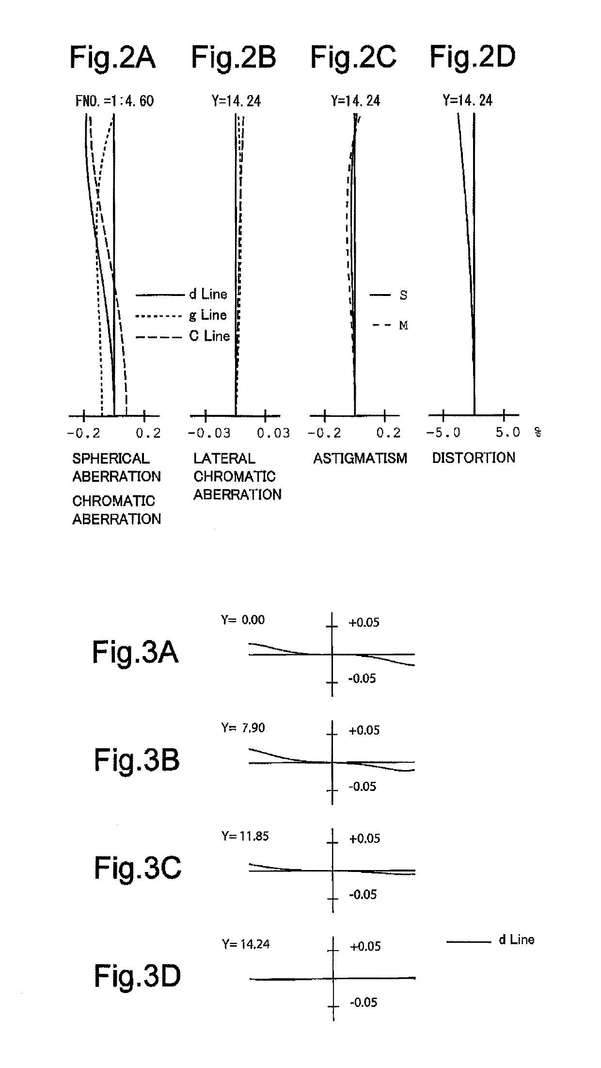
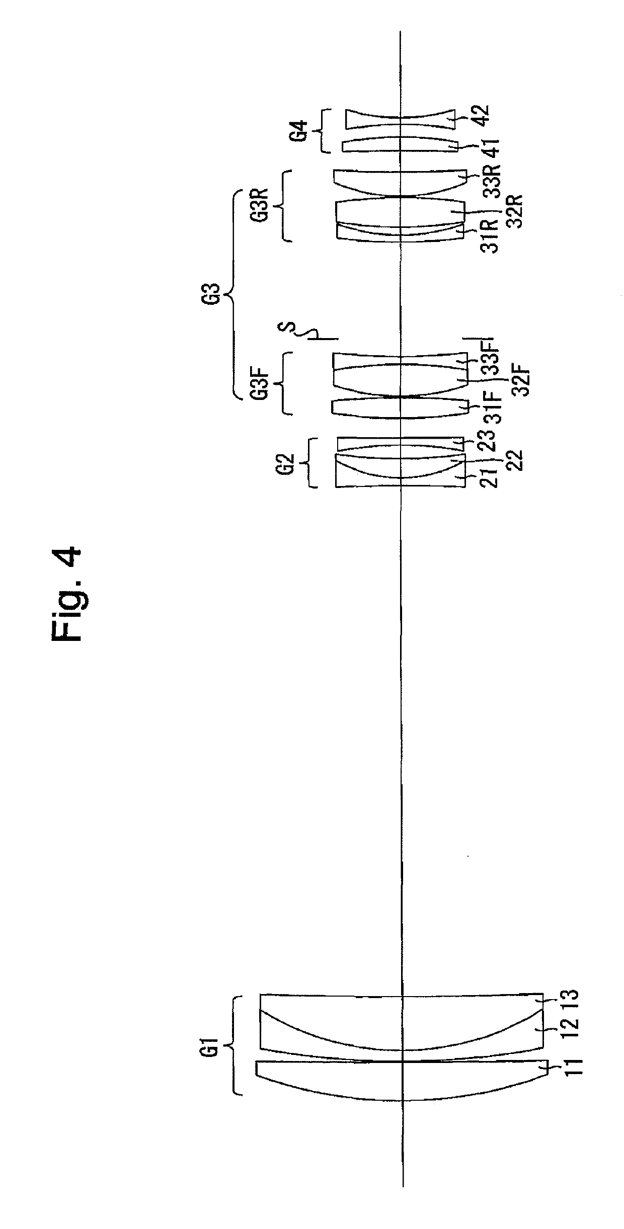
[0191]FIGS. 1 through 6D and Tables 1 through 3 disclose a first numerical embodiment of the zoom lens system according to the present invention. FIG. 1 shows a lens arrangement of the zoom lens system at the short focal length extremity when focused on an object at infinity. FIGS. 2A, 2B, 2C and 2D show various aberrations that occurred in the zoom lens system of FIG. 1. FIGS. 3A, 3B, 3C and 3D show lateral aberrations that occurred in the zoom lens system of FIG. 1. FIG. 4 shows a lens arrangement of the zoom lens system at the long focal length extremity when focused on an object at infinity. FIGS. 5A, 5B, 5C and 5D show various aberrations that occurred in the zoom lens system of FIG. 4. FIGS. 6A, 6B, 6C and 6D show lateral aberrations that occurred in the zoom lens system of FIG. 4. Table 1 indicates the surface data. Table 2 indicates various lens system data. Table 3 indicates lens-group data.

[0192]The zoom lens system of the first numerical embodiment...

embodiment 2

[Numerical Embodiment 2]

[0205]FIGS. 7 through 12D and Tables 4 through 6 disclose a second numerical embodiment of the zoom lens system according to the present invention. FIG. 7 shows a lens arrangement of the zoom lens system at the short focal length extremity when focused on an object at infinity. FIGS. 8A, 8B, 8C and 8D show various aberrations that occurred in the zoom lens system of FIG. 7. FIGS. 9A, 9B, 9C and 9D show lateral aberrations that occurred in the zoom lens system of FIG. 7. FIG. 10 shows a lens arrangement of the zoom lens system at the long focal length extremity when focused on an object at infinity. FIGS. 11A, 11B, 11C and 11D show various aberrations that occurred in the zoom lens system of FIG. 10. FIGS. 12A, 12B, 12C and 12D show lateral aberrations that occurred in the zoom lens system of FIG. 10. Table 4 indicates the surface data. Table 5 indicates various lens system data. Table 6 indicates lens-group data.

[0206]The lens arrangement of the second numeri...

embodiment 3

[Numerical Embodiment 3]

[0215]FIGS. 13 through 18D and Tables 7 through 9 disclose a third numerical embodiment of the zoom lens system according to the present invention. FIG. 13 shows a lens arrangement of the zoom lens system at the short focal length extremity when focused on an object at infinity. FIGS. 14A, 14B, 14C and 14D show various aberrations that occurred in the zoom lens system of FIG. 13. FIGS. 15A, 15B, 15C and 15D show lateral aberrations that occurred in the zoom lens system of FIG. 13. FIG. 16 shows a lens arrangement of the zoom lens system at the long focal length extremity when focused on an object at infinity. FIGS. 17A, 17B, 17C and 17D show various aberrations that occurred in the zoom lens system of FIG. 16. FIGS. 18A, 18B, 18C and 18D show lateral aberrations that occurred in the zoom lens system of FIG. 16. Table 7 indicates the surface data. Table 8 indicates various lens system data. Table 9 indicates lens-group data.

[0216]The lens arrangement of the th...


PUM


Abstract

A zoom lens system includes a positive first lens group, a negative second lens group, a positive intermediate lens group, and a negative image-side lens group. Upon zooming from the short to long focal length extremities, a distance between the first and second lens groups increases, and a distance between the second and intermediate lens groups decreases. The image-side lens group consists of two lens elements. The following conditions are satisfied:−6.0<f1 / f2<−4.3,−5.4<f1 / fIMG<−3.9, and0.3<D2 / fw<3.0,f1, f2 and fIMG designate the focal lengths of the first, second and the image-side lens groups, respectively, D2 designates a distance between the second lens group and the intermediate lens group, at the short focal length extremity, fw designates the focal length of the zoom lens system at the short focal length extremity.

Description

BACKGROUND OF THE INVENTION[0001]1. Field of the Invention[0002]The present invention relates to a zoom lens system applied to, e.g., a surveillance camera, a digital camera, and an interchangeable lens.[0003]2. Description of Related Art[0004]In recent years, there has been a demand for a zoom lens system that is miniaturized, has a higher zoom ratio, and has an extended (long) focal length at the telephoto side for photographing distant objects using a high zoom ratio. Furthermore, there is a demand to have a high optical quality for an object distance from infinity through to a close distance. However, generally, a large amount of aberrations (especially spherical aberration) occur in a zoom lens system that includes a telephoto range.[0005]Japanese Unexamined Patent Publication Nos. H11-352401 (Patent Literature 1) and 2012-27261 (Patent Literature 2) each disclose a zoom lens system including a telephoto range and configured of a positive first lens group, a negative second len...

Claims


Application Information

Patent Timeline
Patent Type & Authority Patents(United States)
IPC IPC(8): G02B15/14G02B15/173
CPCG02B15/173G02B15/144105G02B15/145113G02B15/1461
Inventor KOGA, TOMOYA
Owner RICOH IMAGING COMPANY
Why Eureka
Try Eureka